Vehicle cooling system

Inactive Publication Date: 2013-12-05
TOYOTA JIDOSHA KK +1
View PDF8 Cites 15 Cited by
  • Summary
  • Abstract
  • Description
  • Claims
  • Application Information

AI Technical Summary

Benefits of technology

[0015]With the cooling system of the invention described above, supercooling of a heat source is able

Problems solved by technology

As a result, supercooling of the heat source, pressure loss related to the flow

Method used


Image

  • Vehicle cooling system
  • Vehicle cooling system
  • Vehicle cooling system

Examples


Embodiment Construction

[0026]Example embodiments of the invention will be described below with reference to the accompanying drawings. In the following description, like or corresponding parts will be denoted by like reference characters, and detailed descriptions of those parts will not be repeated.

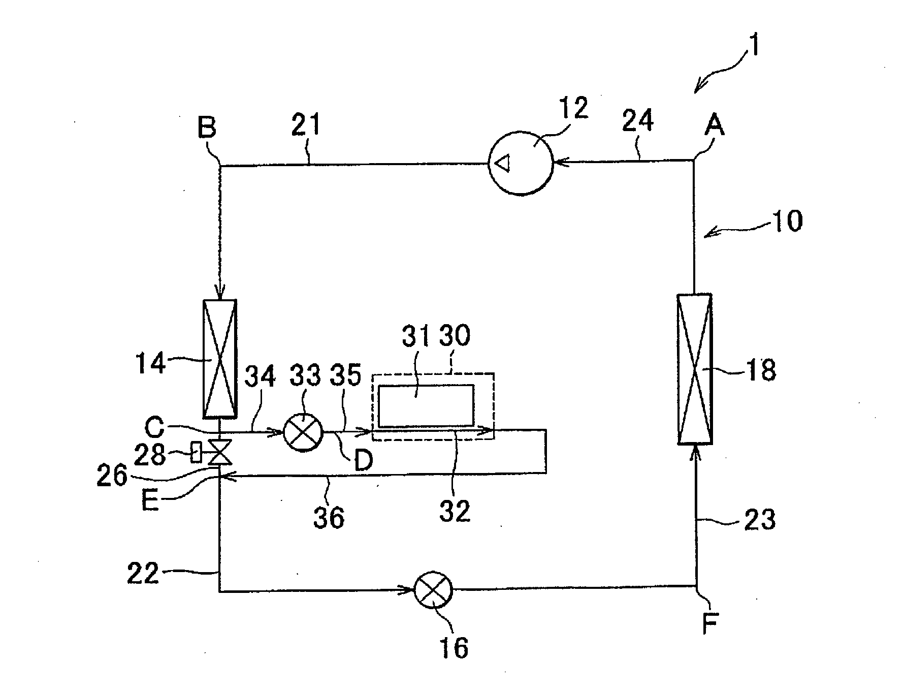
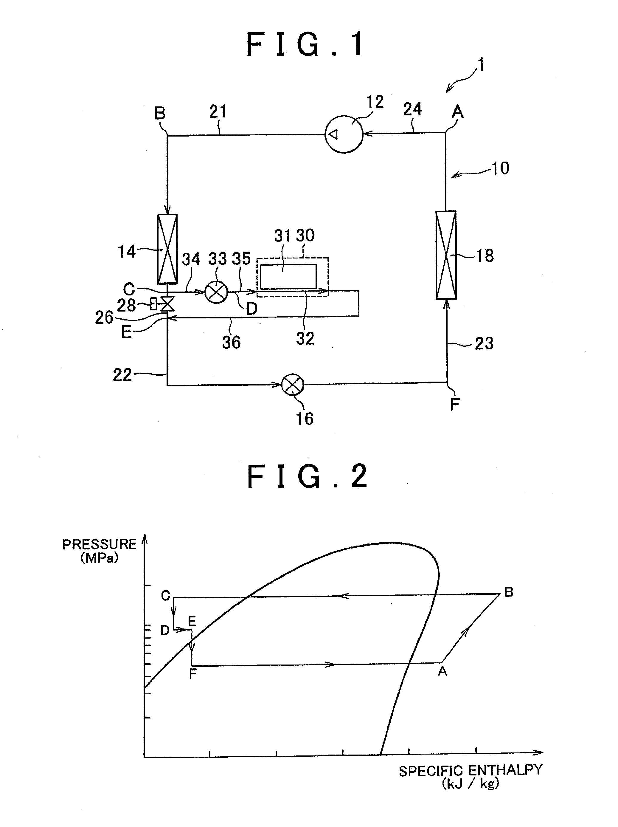
[0027]FIG. 1 is a view of a frame format showing the structure of a cooling system 1 according to a first example embodiment of the invention. As shown in FIG. 1, the cooling system 1 includes a vapor compression refrigeration cycle 10. This vapor compression refrigeration cycle 10 is provided in a vehicle in order to cool the interior of the vehicle, for example. Cooling using the vapor compression refrigeration cycle 10 is performed when, for example, a switch for performing cooling is turned on, or when an automatic control mode that automatically adjusts the temperature in the cabin of the vehicle so that it comes to match a set temperature is selected and the temperature in the vehicle cabin is higher tha...


PUM


Abstract

A cooling system includes a compressor that circulates refrigerant; a condenser that condenses the refrigerant; an expansion valve that reduces a pressure of the refrigerant that has been condensed by the condenser; an evaporator that vaporizes the refrigerant that has been reduced in pressure by the expansion valve; a refrigerant passage through which the refrigerant flows from an outlet of the condenser toward an inlet of the expansion valve, and that includes a passage forming portion that forms part of the refrigerant passage; a second passage that is connected in parallel with the passage forming portion; a cooling portion that is provided in the second passage and cools a heat source using the refrigerant; and an expansion valve that is arranged upstream of the cooling portion in the second passage.

Description

BACKGROUND OF THE INVENTION[0001]1. Field of the Invention[0002]The invention relates to a cooling system. More particularly, the invention relates to a cooling system that cools a heat source using a vapor compression refrigeration cycle.[0003]2. Description of Related Art[0004]In recent years, hybrid vehicles, fuel cell vehicles, and electric vehicles and the like that run using the driving force of an electric motor have become attractive as a way to address environmental concerns. In these types of vehicles, electrical equipment such as a motor, generator, inverter, converter, and battery generate heat by the sending and receiving electric power. Therefore, this electrical equipment must be cooled.[0005]Thus, technology has been proposed to cool a heat generating body using a vapor compression refrigeration cycle that is used for a vehicle air conditioner. For example, Japanese Patent Application Publication No. 11-23081 (JP-A-11-23081) describes a system that cools heat generat...

Claims


Application Information

Patent Timeline
IPC IPC(8): F25B1/00
CPCF25B1/00B60H1/00278B60H1/323B60H2001/00307B60H2001/00949F25B31/006F25B5/04F25B2341/0012F25B2600/2511B60H2001/3298
Inventor KAWASE, YASUHIROOHNO, YUICHIUCHIDA, KAZUHIDEKAWAKAMI, YOSHIAKIJOJIMA, YUKITAKAHASHI, EIZOSATO, KOUSUKE
Owner TOYOTA JIDOSHA KK
Why Eureka
Try Eureka