Method, device, computer program and information storage means for transmitting a source frame into a video display system

a video display system and source frame technology, applied in the field of multi-projector video systems, to achieve the effect of optimizing the end-to-end display latency

Inactive Publication Date: 2013-12-05
CANON KK
View PDF5 Cites 27 Cited by
  • Summary
  • Abstract
  • Description
  • Claims
  • Application Information

AI Technical Summary

Benefits of technology

[0022]A main advantage to this method is removal of superfluous latency between the video source data delivery from the video source device and the display of those data on the screen: the latency is optimized, the optimization taking account of the multi-projection system configuration. At the same time, a tight and correct synchronization is kept between all projector displays, thereby avoiding visual artifacts.
[0028]An advantage to this method is that a sub-frame rotation process, when needed, is done on the fly during video data reception. Thus, this processing does not generate extra latency.
[0064]A main advantage to this method is removal of superfluous latency between the video source data delivery from the video source device and the display of those data on the screen: the latency is optimized, the optimization taking account of the multi-projection system configuration. At the same time, a tight and correct synchronization is kept between all projector displays, thereby avoiding visual artifacts.
[0068]An advantage to this method is that a sub-frame rotation process, when needed, is done on the fly during video data reception. Thus, this processing does not generate extra latency.

Problems solved by technology

This results in a situation where all the projectors constituting the system do not have the same orientation.
This latency may be critical for a real time application such as video gaming, flight simulator, etc. and comprises a problem of the video display system.

Method used


Image

  • Method, device, computer program and information storage means for transmitting a source frame into a video display system
  • Method, device, computer program and information storage means for transmitting a source frame into a video display system
  • Method, device, computer program and information storage means for transmitting a source frame into a video display system

Examples


Embodiment Construction

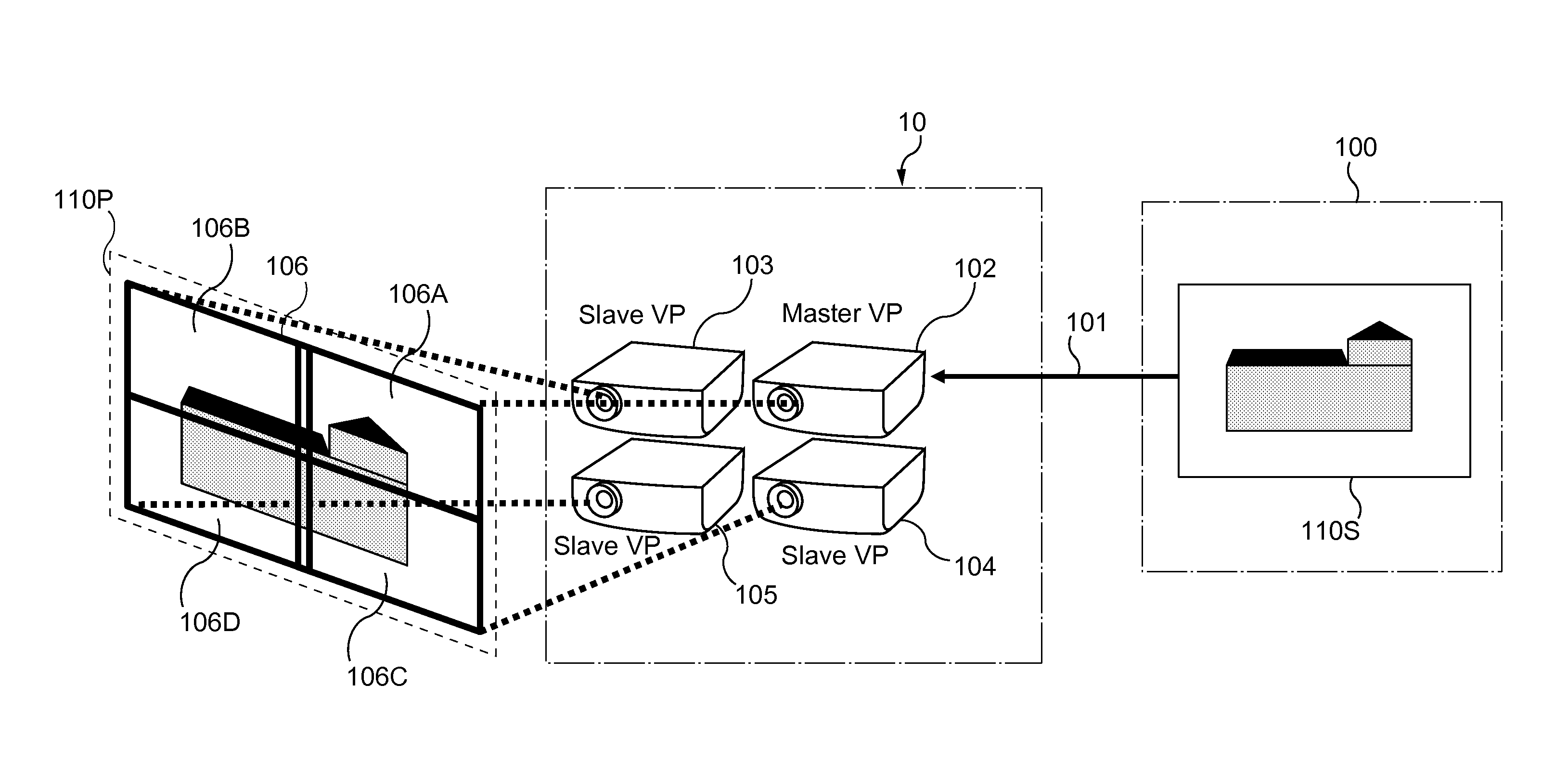
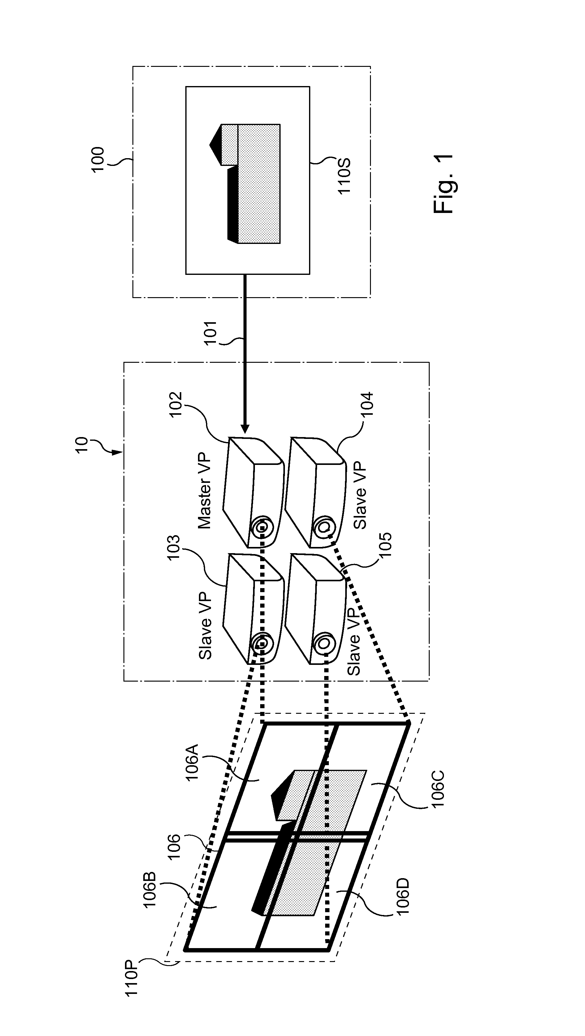
[0088]FIG. 1 shows an example of a wireless multi-projection video system 10 capable of implementing one or more embodiments of the current invention. The video system is illustrated as a wireless system, but the invention can equally be implemented on a system with a wired connection for data transfer from a source device. The video system 10 comprises a plurality of communication and display devices 102, 103, 104 and 105 embodied in video projectors. The video projectors further comprise a master projector 102 arranged in cooperation with a plurality of slave projectors 103, 104 and 105.

[0089]Using such a system, the user is able to manage the display of high quality video (for example 4k2k video: with an associated size image comprising 3840×2160 pixels) on a large area with standard video projector devices (able to support 1080p HD video 1920×1080 pixels).

[0090]In the exemplary system described, video input (4k2k video) is provided by a video source device 100 to one video proje...


PUM


Abstract

Method, device, computer program and information storage means for transmitting a source frame into a video display system, the video display system (10) comprising a plurality of projectors, the video display system (10) further arranged to produce a projected image (106) from the source frame (100), each projector (102, 103, 104, 105) arranged to display a sub-frame (106A, 106B, 106C, 106D) of the projected image (106). The video display system further comprises capability to arrange a display delay, equal to a delay between reception of a source frame synchronization signal and a sub-frame display synchronization signal, dependent on the positions and the orientations of the video projectors, such that display of the projected image begins before at least one projector has received an associated complete sub-frame.

Description

[0001]This application claims priority under 35 U.S.C. §119(a)-(d) of United Kingdom Patent Application No. 1209683.0, filed on May 31, 2012 and entitled “Method, device, computer program and information storage means for transmitting a source frame into a video display system”. The above cited patent application is incorporated herein by reference in its entirety.FIELD OF THE INVENTION[0002]The invention relates to the field of video display systems, more particularly to multi projector video systems.[0003]The invention further relates to the transmission of a source frame into such a system and the division and processing of the source frame by the system.BACKGROUND OF INVENTION[0004]The present invention relates to a video display system, comprising a multi projector (MP) arrangement, capable of distributing sub-frames of images between a plurality of VP (video projectors).[0005]Consider a video projection system comprising multiple projectors arranged to generate adjacent, parti...

Claims


Application Information

Patent Timeline
Patent Type & Authority Applications(United States)
IPC IPC(8): H04N5/04
CPCH04N5/04H04N9/3147G09G5/399H04N9/3185H04N9/3194G06F3/1446G09G3/002G09G2340/0407G09G2370/12G03B21/00G09G5/12H04N5/74H04N9/3179
Inventor HALNA DU FRETAY, TRISTANINOHIZA, HIROHIKO
Owner CANON KK
Why Eureka
Try Eureka