Electrical device

a technology of electric devices and housings, applied in the direction of electrical apparatus construction details, casings/cabinets/drawers, casings/cabinets/drawers details, etc., can solve the problems of difficult to secure high contact pressure, large contact resistance between the main body and the lid, and leakage of electromagnetic noise generated by electrical components outside the housing via the gap, etc., to improve the effect of electromagnetic shielding and contact pressur

Active Publication Date: 2013-12-05
NIPPON SOKEN +1
View PDF9 Cites 25 Cited by
  • Summary
  • Abstract
  • Description
  • Claims
  • Application Information

AI Technical Summary

Benefits of technology

[0013]With the above configuration, the main body and the lid of the housing make contact with each other at the protrusions in the vertical direction. Moreover, the lid is fastened by the fastening means to the main body also in the vertical direction. That is, the direction of contact between the main body and the lid at the protrusions coincides with the direction of fastening the lid to the main body. Consequently, it is possible to increase the contact pressure between the main body and the lid at the protrusions, thereby lowering the contact resistance between the main body and the lid. As a result, it is possible to improve the effect of electromagnetically shielding the at least one electrical component by the housing.
[0014]Moreover, with the direction of contact between the main body and the lid at the protrusions coincident with the direction of fastening the lid to the main body, it is possible to stabilize the fixed state of the main body and the lid, thereby suppressing rattling noise caused by vibration between the main body and the lid.
[0015]Furthermore,

Problems solved by technology

Furthermore, in the housing, there may be a gap formed between the main body and the lid; thus, the electromagnetic noise generated by the electrical components may leak outside of the housing via the gap.
Consequently, it may be difficult to secure high contact pressure between the main body and the lid at the raised portions, and thus the contact resistance between the main body and the lid may tend to be large.
However, in this case, with the small distances between the facing pairs of the sidewalls of the lid, it would be difficult to fit the lid onto the main body, thus lowering the productivity.
Moreover, with the directions of contact between the main body and the lid at the raised portions perpendicular to the direction of fixing the lid to the main body, it may be difficult to stabilize the fixed state of the main body and the lid.
Co

Method used


Image

  • Electrical device
  • Electrical device
  • Electrical device

Examples


first embodiment

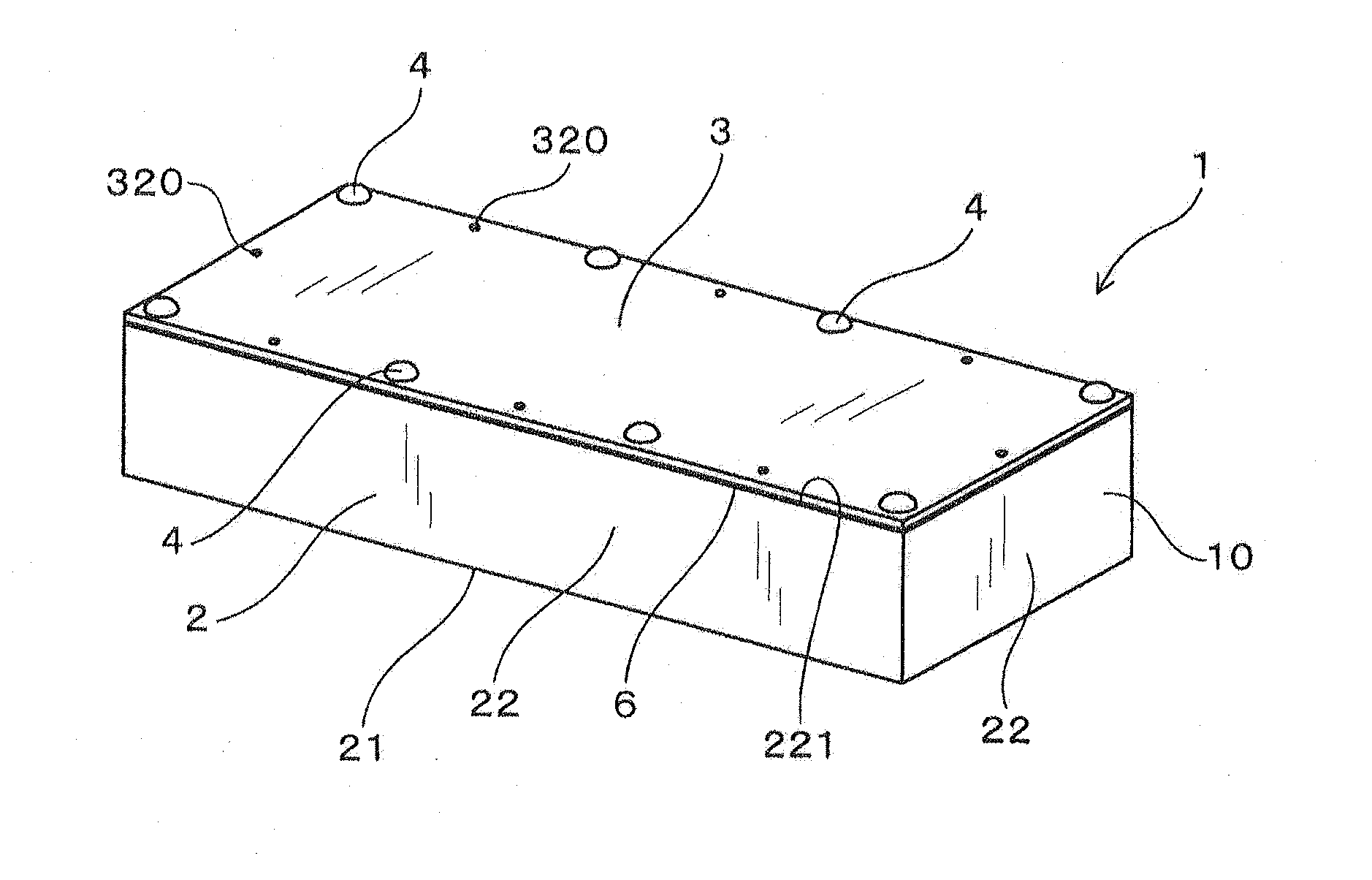
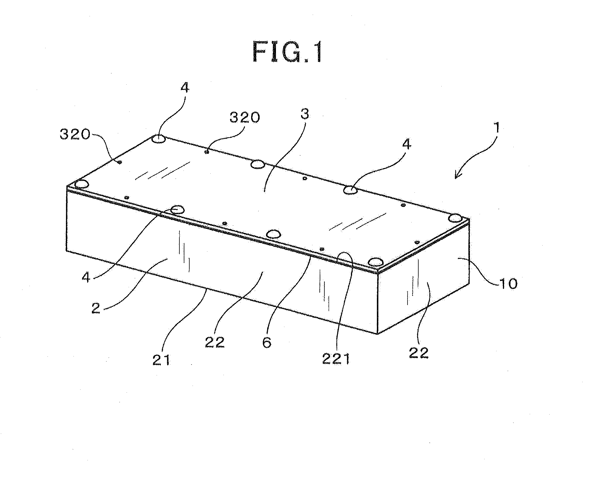
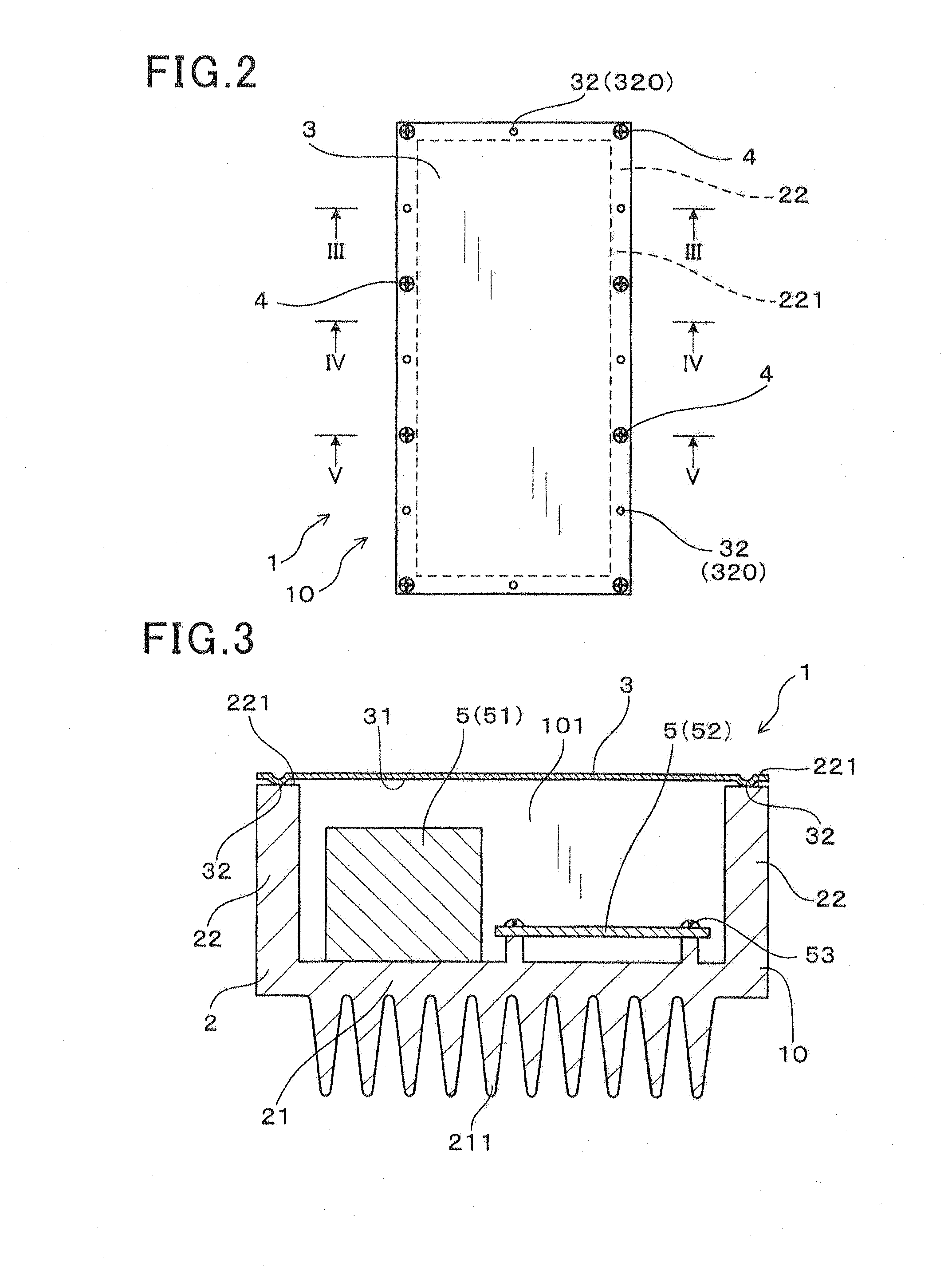
[0062]Referring to FIGS. 1-5, an electrical device 1 according to a first embodiment includes a housing 10 that is comprised of a main body 2 and a lid 3, means for fastening the lid 3 to the main body 2 of the housing 10, and a plurality of electrical components 5 received in the housing 10.

[0063]The main body 2 of the housing 10 has a bottom wall 21 and a circumferential sidewall 22 that is formed along the entire circumferential periphery of the bottom wall 21 so as to stand upward from the bottom wall 21. The lid 3 is fixed to a top surface 221 of the sidewall 22 of the main body 2 so as to cover the main body 2 from the upper side. More specifically, in the present embodiment, as shown in FIGS. 1-2 and 5, the lid 3 is fastened by a plurality of machine screws 4 to the top surface 221 of the sidewall 22 of the main body 2 at a plurality of predetermined positions; the machine screws 4 together make up the means for fastening the lid 3 to the main body 2 of the housing 10. Moreov...

second embodiment

[0088]This embodiment illustrates an electrical device 1 which has almost the same structure as the electrical device 1 according to the first embodiment; accordingly, only the differences therebetween will be described hereinafter.

[0089]As described previously, in the electrical device 1 according to the first embodiment, the protrusions 32 are formed on the bottom surface 31 of the lid 3 so as to have the substantially hemispherical shape (see FIG. 8). Consequently, when viewed upward from the lower side, each of the protrusions 32 has a substantially circular shape (see FIG. 7).

[0090]In comparison, in the electrical device 1 according to the present embodiment, the protrusions 32 are formed on the bottom surface 31 of the lid 3 so as to have a substantially cuboid shape. Consequently, as shown in FIGS. 9 and 10, when viewed upward from the lower side, each of the protrusions 32 is substantially rectangular-shaped to have a length a in the thickness direction of the sidewall 22 of...

third embodiment

[0096]This embodiment illustrates an electrical device 1 which has almost the same structure as the electrical device 1 according to the first embodiment; accordingly, only the differences therebetween will be described hereinafter.

[0097]As described previously, in the electrical device 1 according to the first embodiment, the protrusions 32 are formed on the bottom surface 31 of the lid 3 so as to have the substantially hemispherical shape (see FIG. 8).

[0098]In comparison, in the electrical device 1 according to the present embodiment, the protrusions 32 are formed on the bottom surface 31 of the lid 3 so as to have a substantially conical, pyramidal or triangular prismatic shape. Consequently, as shown in FIG. 11, the protrusions 32 have a substantially triangular shape in cross section.

[0099]According to the present embodiment, it is possible to achieve the following advantageous effects in addition to those achievable according to the first embodiment.

[0100]In addition, the prot...


PUM


Abstract

An electrical device has a housing that includes a main body and a lid both of which are electrically conductive. The lid is fastened to a top surface of a sidewall of the main body so as to cover the main body. On at least one of a bottom surface of the lid and the top surface of the sidewall of the main body, there are formed a plurality of protrusions at predetermined positions; each of the protrusions abuts against that one of the bottom surface of the lid and the top surface of the sidewall which is opposed to the protrusion. Except at those predetermined positions where the protrusions are formed, there is provided, between the bottom surface of the lid and the top surface of the sidewall of the main body, a gap via which the internal and external spaces of the housing communicate with each other.

Description

CROSS-REFERENCE TO RELATED APPLICATION[0001]This application is based on and claims priority from Japanese Patent Application No. 2012-125876, filed on Jun. 1, 2012, the content of which is hereby incorporated by reference in its entirety into this application.BACKGROUND[0002]1. Technical Field[0003]The present invention relates to electrical devices which include a housing and electrical components received in the housing.[0004]2. Description of the Related Art[0005]For example, in electrical vehicles and hybrid vehicles, there are used electrical devices such as a DC-DC converter and an inverter; those electrical devices include electrical components that form an electric power supply circuit and a housing that receives the electrical components therein. Further, the housing generally has a main body and a lid both of which are electrically conductive, so as to electromagnetically shield the electrical components received in the housing. Consequently, electromagnetic noise generat...

Claims


Application Information

Patent Timeline
IPC IPC(8): H05K9/00H05K5/02
CPCH05K9/0007H05K5/0239H05K7/209H05K9/0009H05K7/14322H05K7/1432H05K5/03
Inventor OHOKA, SHINJIOKUBO, TAKUYAANDO, MIKIHIRO
Owner NIPPON SOKEN
Why Eureka
Try Eureka