Airway device, airway assist device and the method of using same

a technology of airway assist and airway, which is applied in the direction of respirators, applications, diagnostic recording/measuring, etc., can solve the problems of medical professionals not knowing if the proper placement of the laryngeal mask airway has occurred, and the airway may be difficult to be inflated

Active Publication Date: 2013-12-05
WM & DG
View PDF27 Cites 88 Cited by
  • Summary
  • Abstract
  • Description
  • Claims
  • Application Information

AI Technical Summary

Problems solved by technology

This is not a desirable result as the blocking by the epiglottis can cause problems with the airflow through the laryngeal mask airway.
In addition, inappropriate sizing and differences in the anatomy of patients may also impair the proper positioning of the laryngeal mask airway.
Since the insertion is performed blindly, the medical professional will not know if proper placement of the laryngeal mask airway has occurred.
If the epiglottis is at least partially blocking the opening in the tube, this intubation may be difficult.
In addition, the glottis opening quite often does not align with the tube opening which can make this blind insertion difficult and may result in trauma to the laryngeal inlet.

Method used


Image

  • Airway device, airway assist device and the method of using same
  • Airway device, airway assist device and the method of using same
  • Airway device, airway assist device and the method of using same

Examples


first embodiment

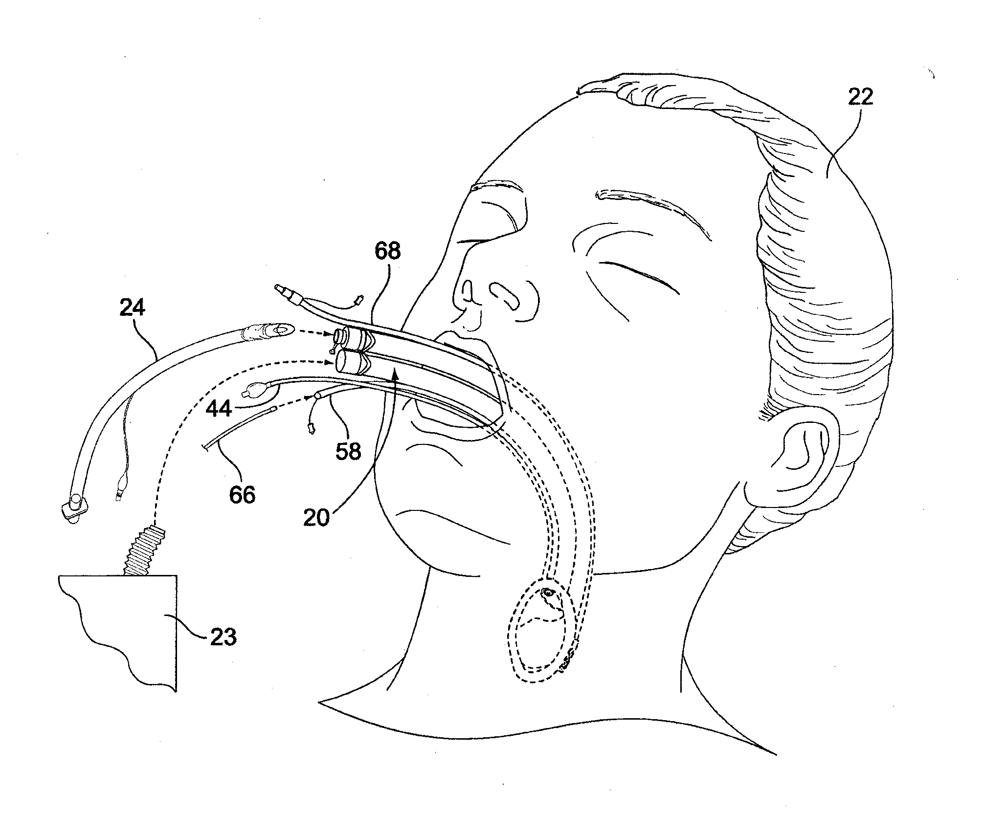
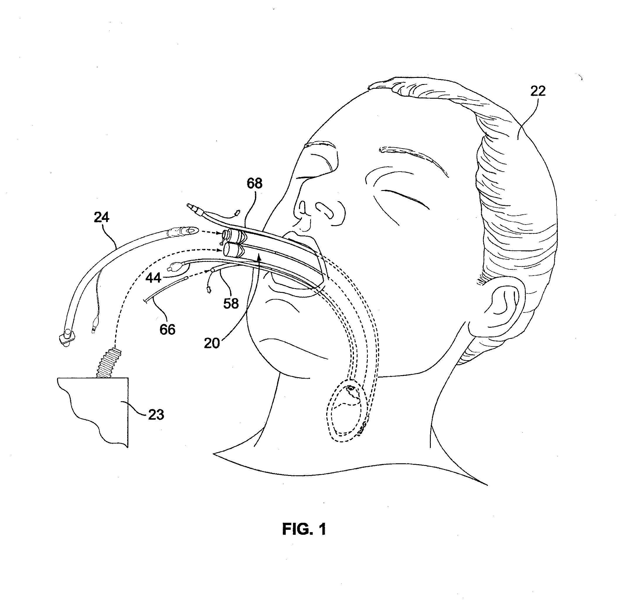
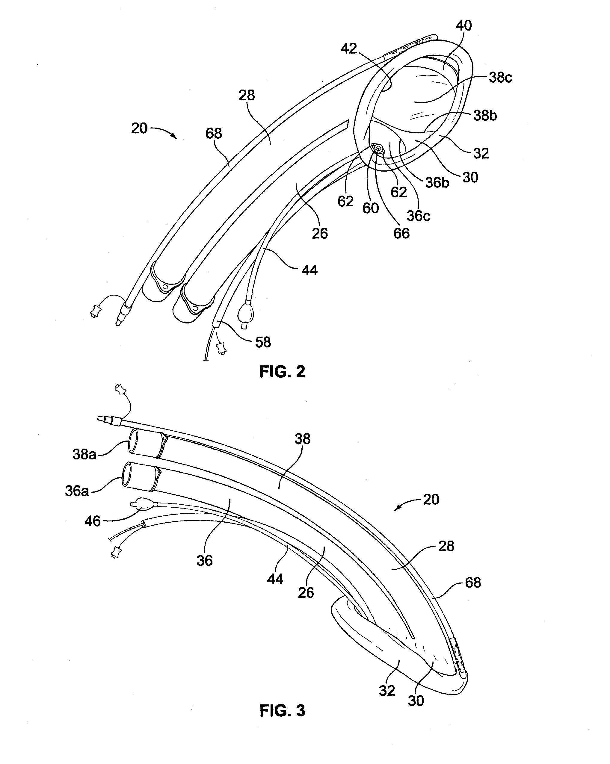
[0030]Attention is invited to the airway device 20 shown in FIGS. 1-8.

[0031]Each tube 26, 28 is formed from a cylindrical wall 36, 38 having a proximal open inlet 36a, 38a (at the end closest to the medical professional), an opposite distal open outlet 36b, 38b (at the end furthest away from the medical professional during use of the airway device 20) and a central passageway 36c, 38c extending through the respective tube 36, 38. Each tube 36, 38 has a centerline 36d, 38d which extends from the proximal inlet 36a, 38a to the distal outlet 36b, 38b. The tubes 26, 28 are curved along the length of each tube 26, 28 and the centerlines 36d, 38d are accordingly curved. Each tube 26, 28 has a diameter which is preferably 15 mm, however, each tube 26, 28 may be bigger or smaller, and / or not of equal diameter with respect to each other. Each tube 26, 28 is formed of a relatively stiff but compliant plastics material and is preferably formed by extrusion. The tubes 26, 28 are situated side-b...

second embodiment

[0042]Attention is now invited to the airway device 120 shown in FIGS. 9 and 10. Each tube 126, 128 is formed from a cylindrical wall 136, 138 having a proximal open inlet 136a, 138a (at the ends closest to the medical professional), an opposite open distal outlet 136b, 138b (at the ends furthest away from the medical professional during use of the airway device 120) and a central passageway 136c, 138c extending through the respective tube 126, 128. Tube 128 is shown in full line in FIG. 9 to illustrate the construction of the tube 128 (of course, in practice, tube 126 may be opaque such that tube 128 would not be visible along its length). The outlets 136b, 138b generally align with each other. Each tube 126, 128 has a centerline 136d, 138d which extends from the proximal inlet 136a, 138a to the distal outlet 136b, 138b. The tubes 126, 128 are curved along the lengths thereof and the centerlines 136d, 138d are accordingly curved. Each tube 126, 128 is formed of a relatively stiff b...


PUM


Abstract

An airway device is provided for opening a patient's airway. The airway device provides dual tubes which allow the patient to breathe on his/her own, to be ventilated, or to be intubated. The airway device includes a camera which provides constant visualization of the patient's tissues during insertion of the airway device and during the entire medical procedure. A transmission lumen monitors heart and breath sounds. Information from the camera and the transmission lumen is relayed to a microprocessor to allow for monitoring which may be remote. An airway assist device may be used with the airway device for properly positioning the patient's tongue is also disclosed. The airway assist device is inserted into the patient's vallecula to manipulate the patient's tongue.

Description

FIELD OF THE INVENTION[0001]The present invention relates to an airway device for allowing a patient to breathe on his / her own, to be ventilated, or to be intubated, and its method of use, and relates to an airway assist device used with the airway device for properly positioning the tongue of a patient and its method of use.BACKGROUND OF THE INVENTION[0002]Laryngeal mask airways are known in the art. A laryngeal mask airway is used to ventilate and to supply anesthetic to a patient during surgery. A laryngeal mask airway is different than an endotracheal tube in that the laryngeal mask airway is positioned in the throat of the patient proximally of the vocal folds, while an endotracheal tube is passed through the vocal folds and is positioned in the patient's trachea.[0003]Laryngeal mask airways of the prior art generally have a tube opening into the center of a generally elliptical dome. The tube is generally straight, but can flex to assume a curved shape. A cuff, which may be in...

Claims


Application Information

Patent Timeline
Patent Type & Authority Applications(United States)
IPC IPC(8): A61M16/04A61B1/04
CPCA61M16/04A61M16/0463A61M2205/3375A61M2205/502A61M2230/04A61B1/0676A61B1/0684A61B1/267A61M16/0409A61M16/042A61M16/0486A61M16/0495A61B1/05A61M16/0488A61B1/044A61B1/06A61B1/00009A61M16/0434A61M2205/3368
Inventor MOLNAR, ROBERTIUSCO, ARCANGELO MICHELE
Owner WM & DG
Why Eureka
Try Eureka