Method for detecting and treating insulation lead-to-housing failures

a technology of insulation lead and failure, applied in the field of scientific and medical methods, can solve the problems of fatal failure of cardioversion or defibrillation, long-term reliability and safety of implantable cardiac lead, and functional failure of corresponding conductor, and achieve the effect of improving the resolution of the “safe” voltag

Active Publication Date: 2013-12-05
LAMBDA NU TECH
View PDF0 Cites 21 Cited by
  • Summary
  • Abstract
  • Description
  • Claims
  • Application Information

AI Technical Summary

Benefits of technology

[0017]The 100 V stepped process provides a better resolution of the “safe” voltage that the insulation can withstand from a partial insulation abrasion. In other embodiments, testing may al...

Problems solved by technology

The long-term reliability and safety of implantable cardiac leads is a significant issue.
Anomalies of conductors in implantable medical devices constitute a major cause of morbidity.
Insulation failures have been known to result in a functional failure of the corresponding conductor.
Functional failure of a pace-sense conductor may result in symptoms caused by loss of pacing functions for bradycardia, cardiac resynchronization, or antitachycardia pacing.
Functional failure of a high-voltage conductor may result in fatal failure of cardioversion or defibrillation.
A false positive clinical diagnosis of insulation failure results in unnecessary lead replacement, with corresponding expense and surgical risk.
In addition to limited sensitivity, present methods for diagnosing lead conductor anomalies have limited specificity resulting in false positive diagnostics.
Evaluation of false positive diagnostics adds cost and work to medical care and may contribute to patient anxiety.
If a false-positive diagnostic is not diagnosed correctly, patients may be subject to unnecessary surgical lead replacement with its corresponding risks.
This third region is a parti...

Method used


Image

  • Method for detecting and treating insulation lead-to-housing failures
  • Method for detecting and treating insulation lead-to-housing failures
  • Method for detecting and treating insulation lead-to-housing failures

Examples


Embodiment Construction

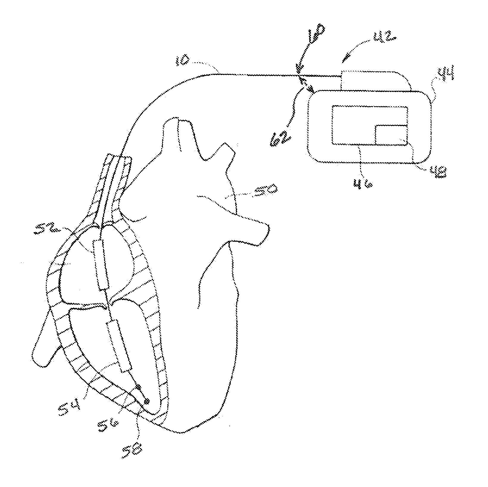
[0026]Disclosed is a method for diagnosis of conductor anomalies, such as insulation failures resulting in the shorting of a defibrillation pathway, in an implantable medical device, such as an implantable cardioverter defibrillator (ICD). Shorted defibrillation pathways are detected by measuring the impedance of the individual defibrillation pathways. If a short is identified, one electrode from the defibrillation circuit is excluded thus delivering defibrillation current only between functioning defibrillation electrodes.

[0027]Modern ICDs routinely deliver low voltage, on the order of 5 volts to 15 volts, pulses or switched AC pulse trains to assess electrical integrity of the high voltage shock pathway. However, clinical case reports indicate that life threatening insulation failures may not be detected by these low voltage measurements. Patients have died when shocks have short circuited, preventing the shock energy from reaching the heart and defibrillating ventricular fibrilla...


PUM


Abstract

Disclosed is a method for the diagnosis of conductor anomalies, such as an insulation failure resulting in a short circuit, in an implantable medical device, such as an implantable cardioverter defibrillator (ICD). Upon determining if a specific defibrillation pathway is shorted, the method excludes the one electrode from the defibrillation circuit, delivering defibrillation current only between functioning defibrillation electrodes. Protection can be provided against a short in the right-ventricular coil-CAN defibrillation pathway of a pectoral, transvenous ICD with a dual-coil defibrillation lead. If a short caused by an in-pocket abrasion is present, the CAN is excluded from the defibrillation circuit, delivering defibrillation current only between the right-ventricular and superior vena cava defibrillation coils. Determination that the defibrillation pathway is shorted may be made by conventional low current measurements or delivery of high current extremely short test pulses.

Description

RELATED APPLICATION[0001]The present application claims the benefit of U.S. Provisional Application No. 61 / 689,191 filed Jun. 1, 2012, which is incorporated herein in its entirety by reference.FIELD OF THE INVENTION[0002]The present invention relates, generally, to scientific and medical methods. More particularly, the invention relates to methods for diagnosis of conductor anomalies. Most particularly, the invention relates to a method for diagnosis of conductor anomalies, such as insulation failures resulting in the shorting of a defibrillation pathway or circuit, in an implantable medical device, such as an implantable cardioverter defibrillator (ICD). Shorted defibrillation pathways are detected by measuring the impedance of the individual defibrillation pathways. If a short is identified, one electrode from the defibrillation circuit is excluded thus delivering defibrillation current only between functioning defibrillation electrodes.BACKGROUND[0003]The long-term reliability an...

Claims


Application Information

Patent Timeline
IPC IPC(8): A61N1/39
CPCA61N1/3925A61N1/37A61N1/3931A61N1/3956A61N1/0563A61N1/3906
Inventor KROLL, MARK WILLIAMSWERDLOW, CHARLES DENNIS
Owner LAMBDA NU TECH
Why Eureka
Try Eureka