Abdominal cavity-vein shunt stent

a technology of shunt stent and abdominal cavity, which is applied in the field of abdominal cavityvein shunt stent, can solve problems such as damage to the catheter, and achieve the effects of lightening the load on the patient at the time of stent placement and lightening the load on the patient after stent placemen

Inactive Publication Date: 2013-12-05
PIOLAX MEDICAL DEVICES +1
View PDF22 Cites 14 Cited by
  • Summary
  • Abstract
  • Description
  • Claims
  • Application Information

AI Technical Summary

Benefits of technology

[0025]According to the invention, when the differential pressure obtained by subtracting the pressure of the intrahepatic vein from the pressure in the abdominal cavity becomes not lower than the predetermined value due to accumulation of ascites in the abdominal cavity, the one-way valve is opened to drain the ascites into the intrahepatic vein so that excessive ascites accumulated in the abdominal cavity can be transported. When the differential pressure becomes lower than the predetermined value, the one-way valve is closed to prevent the blood flowing in the intrahepatic vein from flowing out to the abdominal cavity side. In this manner, the pressure in the abdominal cavity can be kept at a constant value.
[0026]The stent may function well as long as one end of the stent body is disposed in the intrahepatic vein and the other end of the stent body passes through the liver parenchyma so as to be disposed in the abdominal cavity. Because the stent can be placed by an intravascular operation performed by a guide wire, a catheter or the like, the load imposed on the patient at the time of placement of the stent can be lightened. Because one end of the stent body is disposed in the intrahepatic vein and the other end of the stent body is disposed in the abdominal cavity near the liver, the stent is relatively short so that the load imposed on the patient after placement of the stent can be lightened.

Problems solved by technology

Further, there is a possibility that the catheter may be damaged by body motion, an external injury, etc.

Method used


Image

  • Abdominal cavity-vein shunt stent
  • Abdominal cavity-vein shunt stent
  • Abdominal cavity-vein shunt stent

Examples


Embodiment Construction

[0032]An embodiment of an abdominal cavity-vein shunt stent according to the invention will be described below with reference to the drawings.

[0033]As shown in FIGS. 3 and 4, the abdominal cavity-vein shunt stent 10 (“stent 10”) is provided for transporting ascites accumulated in the inside of the abdominal cavity 1 to a vascular system. The stent 10 extends cylindrically long and has a stent body 30 which has one end to be disposed in the intrahepatic vein 3a of the liver 3, and the other end for passing through the liver parenchyma 3b to be disposed in the abdominal cavity 1.

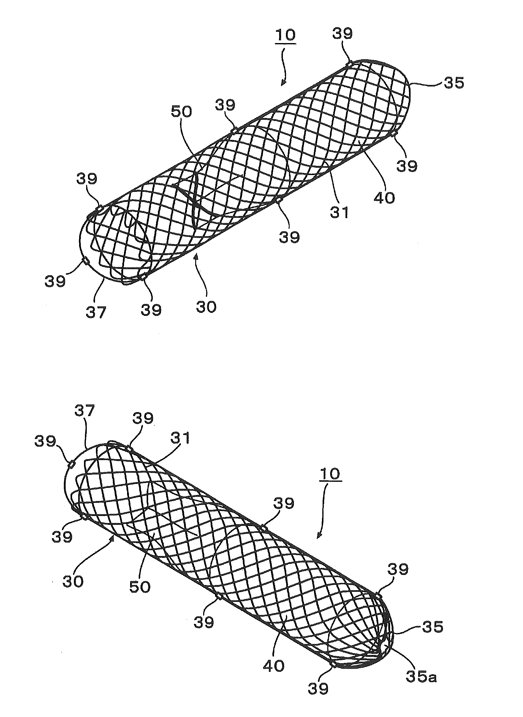
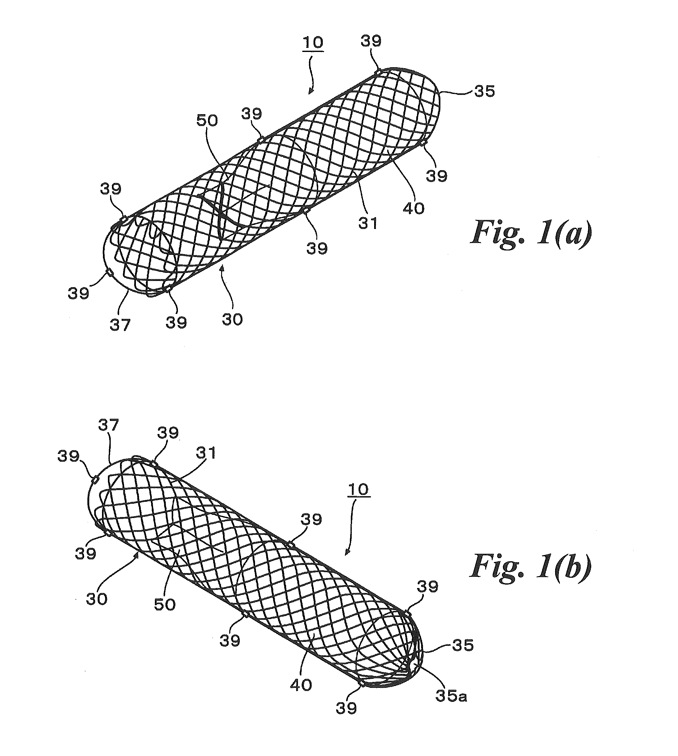
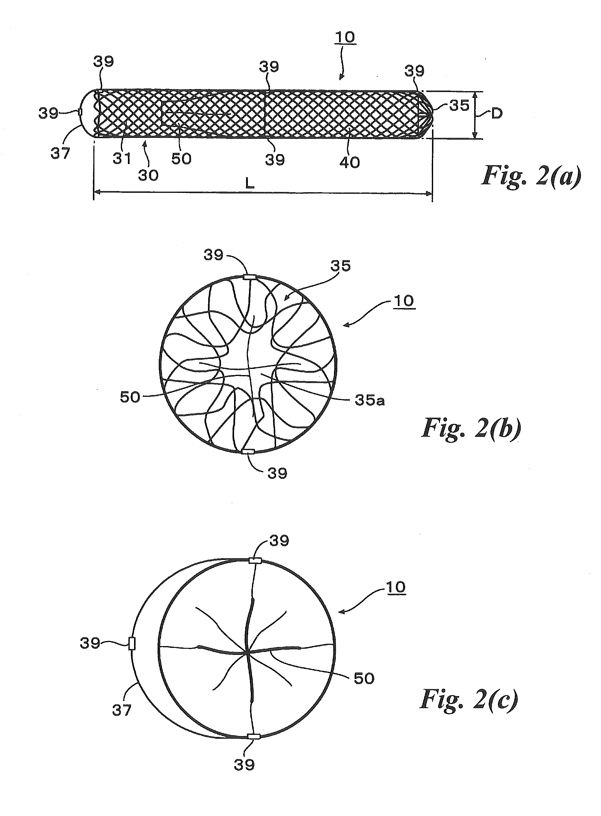
[0034]Referring also to FIGS. 1 and 2, the stent body 30 in this embodiment is formed into a cylindrical shape by braiding and / or enlacing wire 31 having a predetermined diameter. The stent body 30 is shaped like mesh having a predetermined pattern, and is of a so-called self-expanding type, that is, diametrically contracts with application of external force but diametrically expands in the free state without ...


PUM


Abstract

An abdominal cavity-vein shunt stent provided for transporting ascites accumulated in the abdominal cavity of a patient to a vascular system, includes: a stent body which extends cylindrically long and which has one end disposed in the intrahepatic vein, and the other end piercing the liver parenchyma and disposed in the abdominal cavity; and a one-way valve which is disposed in the stent body, which is opened to drain ascites into the intrahepatic vein when a differential pressure obtained by subtracting the pressure of the intrahepatic vein from the pressure in the abdominal cavity is not lower than a predetermined value, and which is closed when the differential pressure is lower than the predetermined value.

Description

TECHNICAL FIELD[0001]The present invention relates to an abdominal cavity-vein shunt stent for transporting ascites accumulated in the abdominal cavity of a patient to a vascular system.BACKGROUND ART[0002]Ascites may be accumulated in the abdominal cavity because of peritonitis, cirrhosis, cancer, etc. Among various measures to deal with the ascites, one measure is to reduce ascites by forcibly draining water in the body as urine using diuretics, and another measure is to directly remove ascites by inserting a tube in the abdominal cavity. However, since ascites includes leukocytes, proteins, etc., it is not preferable in many cases that ascites is drained from the body simply.[0003]Therefore, a method of placing a catheter in the body for the purpose of returning ascites back into the body without draining the ascites has been put into practical use. The abdominal cavity-vein shunt catheter has a chamber provided with a check valve, a venous tube connected to one end of the chambe...

Claims


Application Information

Patent Timeline
Patent Type & Authority Applications(United States)
IPC IPC(8): A61F2/82A61F2/07
CPCA61F2/82A61F2/2418A61F2/2475A61M27/002A61M39/22A61M2202/0401A61F2220/005A61F2220/0058A61F2/07A61F2/90
Inventor ARAI, YASUAKISAKAI, SHINICHI
Owner PIOLAX MEDICAL DEVICES
Why Eureka
Try Eureka