Methods and Systems for Leak Testing

a leak detection and leakage technology, applied in the field of leak detection, can solve the problems of product failure, customer impact, product failure, etc., and achieve the effects of speed and defect detection, speed and accuracy enhancement, and speed and leak detection

Inactive Publication Date: 2013-12-05
SCIEMETRIC INSTR
View PDF27 Cites 15 Cited by
  • Summary
  • Abstract
  • Description
  • Claims
  • Application Information

AI Technical Summary

Benefits of technology

[0012]It is an object of the present invention to enhance leak testing and more specifically to enhancing accuracy, speed and defect detection.

Problems solved by technology

Leak rate testing is an engineering challenge where on the one hand, engineers must meet strict leak rate standards on a wide range of products and systems from semiconductor packages through medical product packaging to chemical storage vessels and liquid / gas handling systems.
On the other hand, they have to make the leak testing process low cost and independent of operator whilst in many applications making the process automated and fast as this step may otherwise become a manufacturing bottleneck.
Product leaks are typically caused by open flow paths, such as pinholes, broken seals or material porosity and in most cases the product leak is a very small flow.
Whilst increased speed (reduced time) of leak testing reduces cost per unit a corresponding reduction in accuracy from this may lead to increased costs from yield (as rejections may actually have passed with an increased accuracy test) and / or product failures and customer impact (as products failing at the customer which were incorrectly passed impact yield, customer satisfaction, and in critical cases may lead directly to damages payable by the manufacturer.
Additionally some scenarios present further issues, such as for example large volume leak testing.
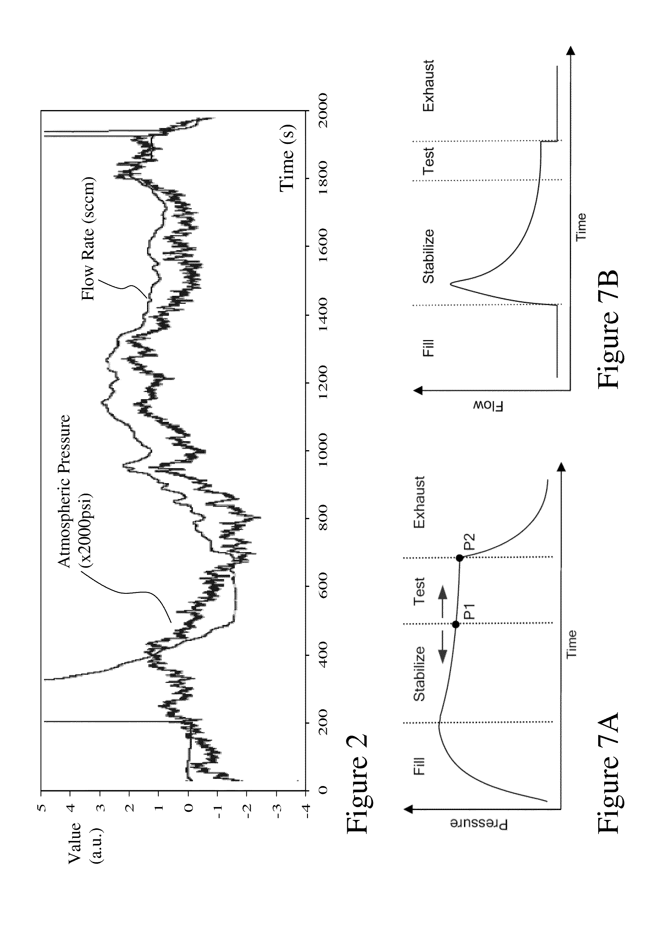
Leak testing with large part volumes in the 30 L (˜7.9 gallons) and above range, creates additional challenges including temperature sensitivity and pressure sensitivity.
This is a large error if the goal is to read down to flow rates of 2 sccm reliably.
Such issues combined with the continued drive for more accurate leak test results, due to increased attention to quality, means that new control / measurement techniques are required.

Method used


Image

  • Methods and Systems for Leak Testing
  • Methods and Systems for Leak Testing
  • Methods and Systems for Leak Testing

Examples


Embodiment Construction

[0051]The present invention is directed to leak testing and more specifically to enhancing accuracy, speed and defect detection.

[0052]The ensuing description provides exemplary embodiment(s) only, and is not intended to limit the scope, applicability or configuration of the disclosure. Rather, the ensuing description of the exemplary embodiment(s) will provide those skilled in the art with an enabling description for implementing an exemplary embodiment. It being understood that various changes may be made in the function and arrangement of elements without departing from the spirit and scope as set forth in the appended claims.

[0053]A “device under test” (DUT) as used herein and throughout this disclosure, refers to an item being tested for a leak. This includes, but is not limited to, devices, components, packages, packaging, containers, piping systems, individual elements, sub-systems and systems requiring that they isolate the interior from the ambient exterior. A DUT may or may...


PUM


Abstract

Leak rate testing is an engineering challenge where on the one hand, engineers must meet strict leak rate standards on a wide range of products and systems from semiconductor packages through medical product packaging to chemical storage vessels and liquid/gas handling systems. On the other hand, they have to make the leak testing process low cost and independent of operator whilst in many applications making the process automated and fast as this step may otherwise become a manufacturing bottleneck. Accordingly embodiments of the invention address manufacturing requirements by providing for high accuracy flow based leak testing of large volumes, providing adaptive techniques for use during testing, providing equivalent circuit modeling techniques allowing optimization and parameter extraction to be simulated prior to manufacturing commitment, and providing for the automatic tuning of setup parameters.

Description

CROSS-REFERENCE TO RELATED APPLICATIONS[0001]This patent application claims the benefit of U.S. Provisional Patent Application U.S. 61 / 655,624 filed Jun. 5, 2012 entitled “Methods and Systems for Leak Testing”, the entire contents of which are included by reference.FIELD OF THE INVENTION[0002]The present invention relates to leak testing and more specifically to enhancing accuracy, speed and defect detection.BACKGROUND OF THE INVENTION[0003]Leak rate testing is an engineering challenge where on the one hand, engineers must meet strict leak rate standards on a wide range of products and systems from semiconductor packages through medical product packaging to chemical storage vessels and liquid / gas handling systems. On the other hand, they have to make the leak testing process low cost and independent of operator whilst in many applications making the process automated and fast as this step may otherwise become a manufacturing bottleneck. To address these conflicting demands engineers...

Claims


Application Information

Patent Timeline
Patent Type & Authority Applications(United States)
IPC IPC(8): G01M3/26G05D7/06
CPCG01M3/26G05D7/0629
Inventor BRINE, RICHARD MICHELSHEAFF, NATHAN BERNARD
Owner SCIEMETRIC INSTR
Why Eureka
Try Eureka