System and Method for Measuring Well Flow Rate

a well flow rate and flow rate technology, applied in the field of system and method for measuring well flow rate, can solve the problems of measured fluid build-up, limited known method of making well flow rate measurements, and leakage of traveling valves and standing valves, etc., and achieve the effect of enhancing accuracy

Active Publication Date: 2013-12-12
CHEVROU USA INC
View PDF2 Cites 7 Cited by
  • Summary
  • Abstract
  • Description
  • Claims
  • Application Information

AI Technical Summary

Benefits of technology

[0010]The present invention provides a substantially improved system for measurement of the flow rate and totalized production of a producing well. In the method of the present invention, liquid production rate in a pumping well is determined by monitoring the depth of the fluid level within the wellbore. It is applicable to any pump lifted well where it is possible to shut the pump off periodically. Accuracy is enhanced with this method by properly accounting for pump leakage and where pump leakage is either known or can be estimated within reasonable limits or where it is measured during the shut in cycle.

Problems solved by technology

Several problems and limitations of known methods of making these measurements are present.
For example, one known problem with rod pump systems is that the traveling valve and standing valve may leak after a short time in service.
As a result, a measured build-up of fluid cannot solely be attributed to reservoir inflow, but will also include fluid contributed by the valve leaks.
This and other problems contribute to the complexity of the task.
Although this method is generally recognized to be the most accurate means for measuring flow rate, the high cost of such dedicated metering equipment has prevented its use on all but a small fraction of the most important producing wells.
For custody transfer applications where high accuracy is important, the expense of such dedicated metering may be justified, but in most instances, the high cost of the equipment prohibits their selection and use.
This method is often even more expensive than the use of surface mounted equipment because of the high cost of the downhole compatible packaging and of providing connectivity to the downhole meter.
This method further suffers from a lack of reliability and difficulty in accessing and servicing downhole equipment.
This method has been shown to often yield inaccurate results as the pump's performance degrades over time and can vary significantly from unit to unit and over time as a result of changes in fluid properties and other dynamic operating conditions.
Consequently, this approach is not considered broadly reliable or effective in practice.
This method is applicable to rod or beam pumping well applications, and although it does not require additional hardware, it has been shown to give inaccurate results as the pump performance varies due to rod stretch, friction, fluid compressibility, and pump wear over time, which rates vary from well to well.
Additional error may be caused by the presence of internal standing or traveling valve leakage and further due to changes in the rate of valve leakage, and which vary from well to well over time.
While the per well expense of such a system is lower than having a dedicated meter for each well, this system suffers the disadvantage in the time required for the flow to fill the feed line and stabilize to allow an accurate reading of the measured well.
Another disadvantage is that the readings for any well are only done periodically.
Another disadvantage of this system is that actual individual well flow rates have been shown to vary substantially over much shorter periods than the period between such tests due to a myriad of factors.
As described, none of the conventional methods consistently satisfy this requirement.

Method used


Image

  • System and Method for Measuring Well Flow Rate
  • System and Method for Measuring Well Flow Rate
  • System and Method for Measuring Well Flow Rate

Examples


Embodiment Construction

[0023]The following description is presented to enable any person skilled in the art to make and use the invention, and is provided in the context of a particular application and its requirements. Various modifications to the disclosed embodiments will be readily apparent to those skilled in the art, and the general principles defined herein may be applied to other embodiments and applications without departing from the spirit and scope of the present invention. Thus, the present invention is not intended to be limited to the embodiments shown, but is to be accorded the widest scope consistent with the principles and features disclosed herein.

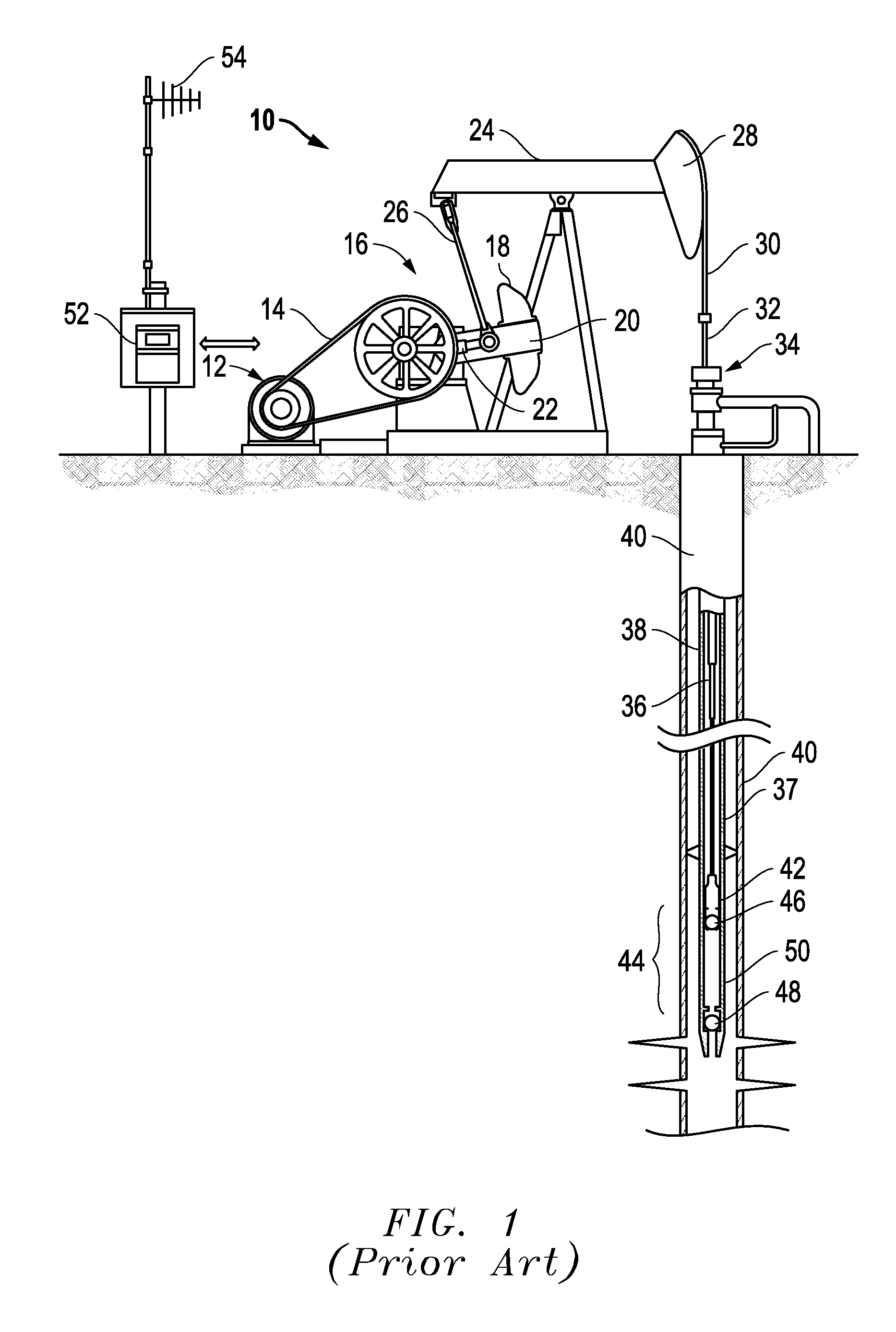
[0024]The present invention uses a typical rod pumping system, as shown as FIG. 1, generally indicated by reference number 10, including a prime mover 12, typically an electric motor. The power output from the prime mover 12 is transmitted by a belt 14 to a gear box unit 16. The gear box unit 16 reduces the rotational speed generated by prime m...


PUM


Abstract

The present invention discloses an improved system for measurement of the liquid flow rate and totalized liquid production of a producing well. In the method of the present invention, liquid production rate in a pumping well is determined by calculation based upon wellbore geometry and continuously monitoring the depth of the fluid level within the wellbore. It is applicable to any pump lifted well where it is possible to shut the pump off periodically. Accuracy is enhanced with this method by properly accounting for pump leakage and where pump leakage is either known or can be estimated within reasonable limits or where it is measured during the pump shut off cycle.

Description

TECHNICAL FIELD OF INVENTION[0001]The present invention relates to a new system and method for measuring fluid flow in liquid producing subterranean wells. The present invention further relates to a system and method that can be applied to existing producing wells without the need to add surface or subsurface flow metering devices, and without the need to connect divertible flow to a central monitoring station. In particular, the present invention provides a system (and alternatives) for electronically assessing the changing height of a liquid level in a well with time, under opposing conditions of pump operation and pump shut-in. Functions developed for cross-sectional area of the well with depth and liquid level with time under the opposing pumping conditions are resolved for a determination of pump flow rate. The results can be used to provide real-time indications of changes in pump condition or operations, as well as long-term changes in reservoir properties.BACKGROUND OF THE I...

Claims


Application Information

Patent Timeline
Patent Type & Authority Applications(United States)
IPC IPC(8): E21B47/00E21B47/04
CPCE21B47/0008E21B47/042G01P3/28G01F1/007G01F23/14G01F23/284G01F23/2962E21B43/127E21B47/10E21B47/009E21B47/047
Inventor HIROSHI, YAMASAKI MARKKING, II, ANDERSON DAVIDPAUL, RUBBO RICHARDCARL, SMITHSON MITCHELL
Owner CHEVROU USA INC
Why Eureka
Try Eureka