Fuel injector

a fuel injector and fuel technology, applied in mechanical equipment, machines/engines, lighting and heating apparatus, etc., can solve the problems of difficult to achieve the formation of the outer diameter dimension of the device is impossible to be reduced, and the failure to form a lean air-fuel mixture having a uniform distribution

Active Publication Date: 2013-12-12
KAWASAKI HEAVY IND LTD
View PDF5 Cites 22 Cited by
  • Summary
  • Abstract
  • Description
  • Claims
  • Application Information

AI Technical Summary

Benefits of technology

[0018]In a further embodiment of the present invention, a swirler for swirling the compressed air about the longitudinal axis may be provided in at least one of the inner main air passage and the outer main air passage. The use of the swirler may make the compressed air swirling about the longitudinal axis to form the premixed air-fuel mixture having a further uniform fuel distribution.

Problems solved by technology

It has, however, been found that with the device disclosed in any of the patent documents 1 and 2 listed above, since the distance of introduction of fuel to the air flow path is short, the fuel distribution tends to be biased towards the neighborhood of the wall surface of the air flow path, failing to form the lean premixed air-fuel mixture having a uniform distribution.
Also, with the device disclosed in the patent document 3 listed above, the respective fuel distributions of the premixed air-fuel mixture from the respective passages are apt to overlap one above the other and, therefore, formation of the lean air-fuel mixture having a uniform distribution is difficult to achieve after all.
In addition, with the device disclosed in the patent document 4 listed above, since the fuel injection unit is located in an outermost peripheral portion of the fuel injector, reduction of the outer diameter dimension of the device is impossible to achieve.

Method used


Image

  • Fuel injector
  • Fuel injector
  • Fuel injector

Examples


Embodiment Construction

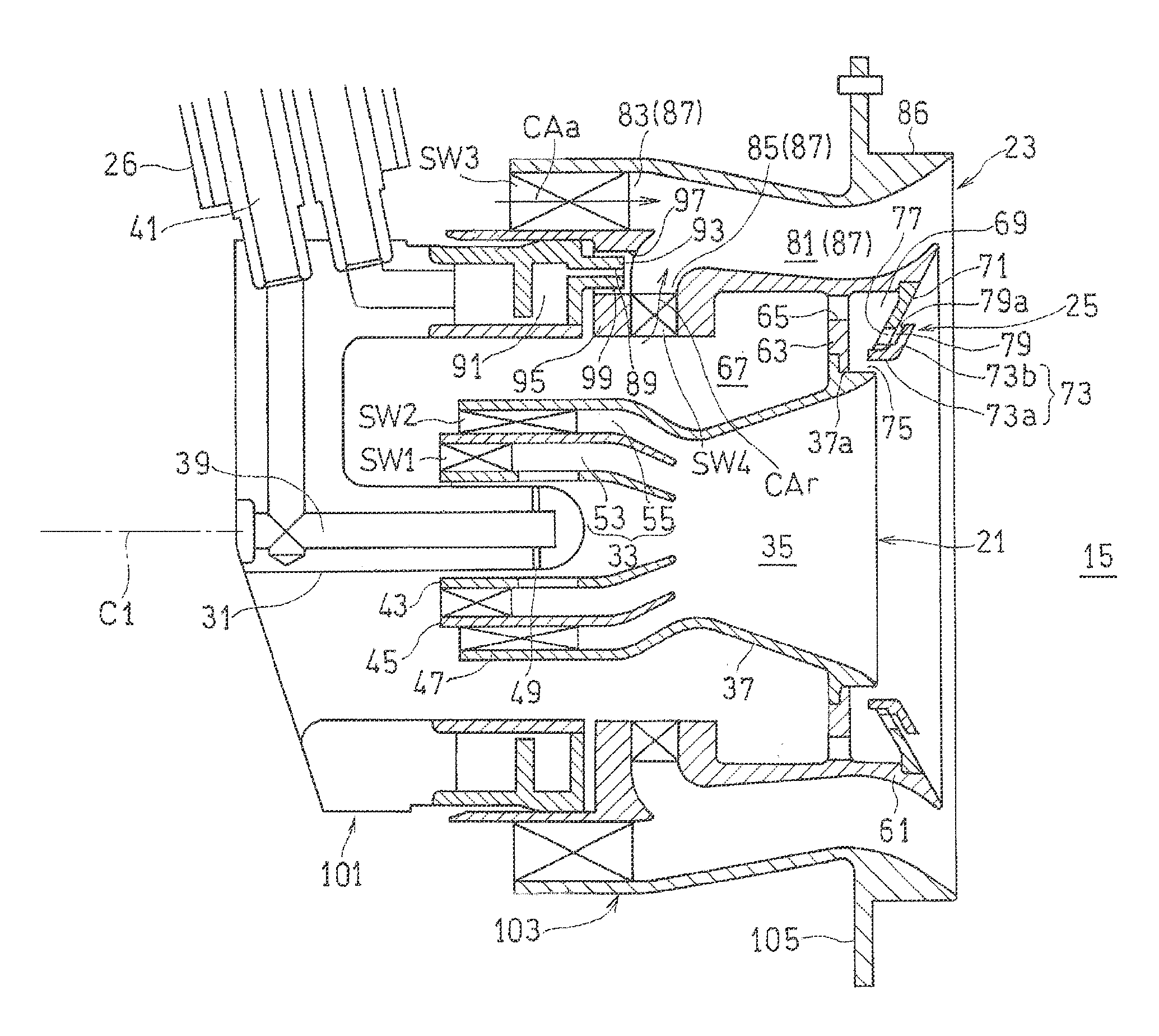
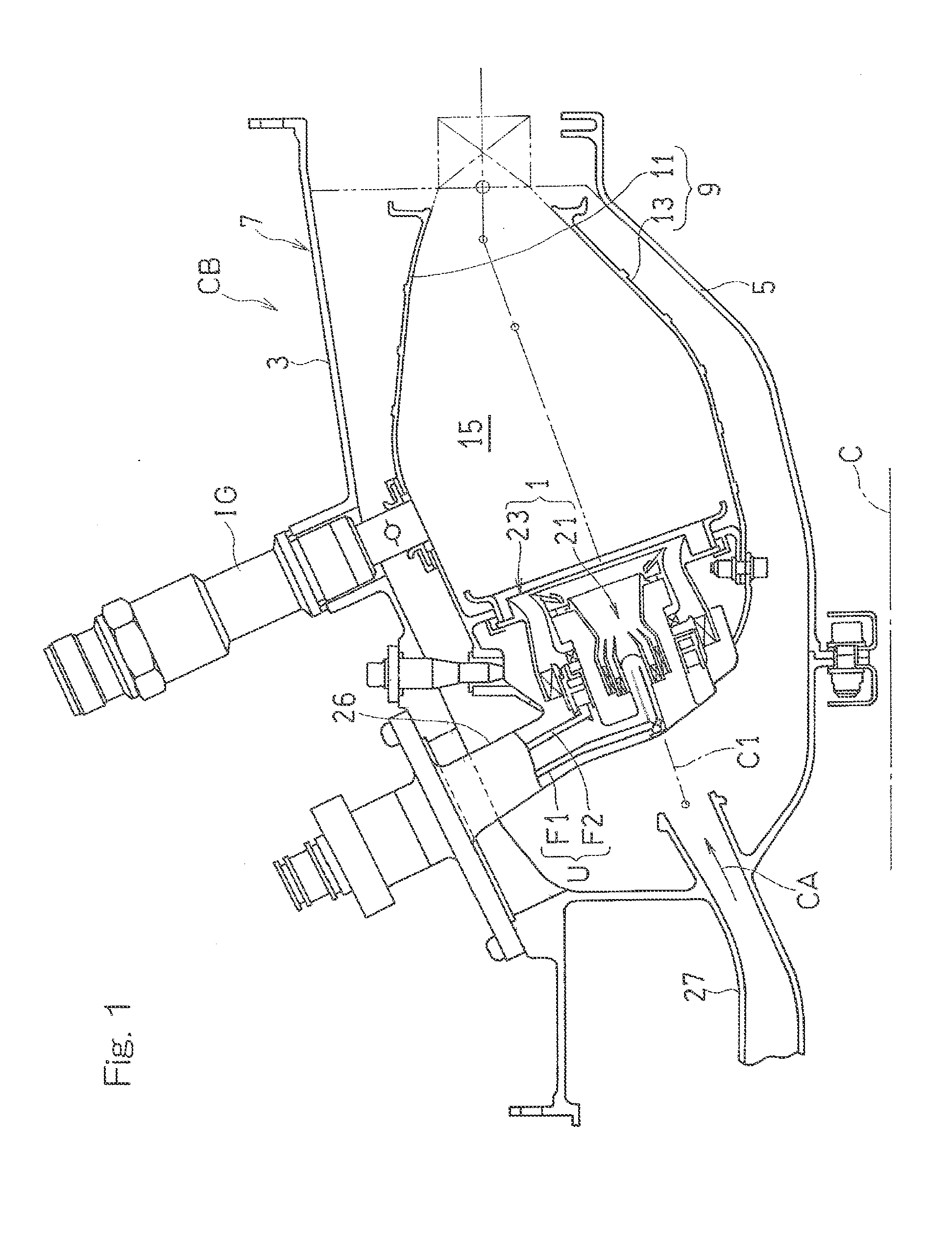
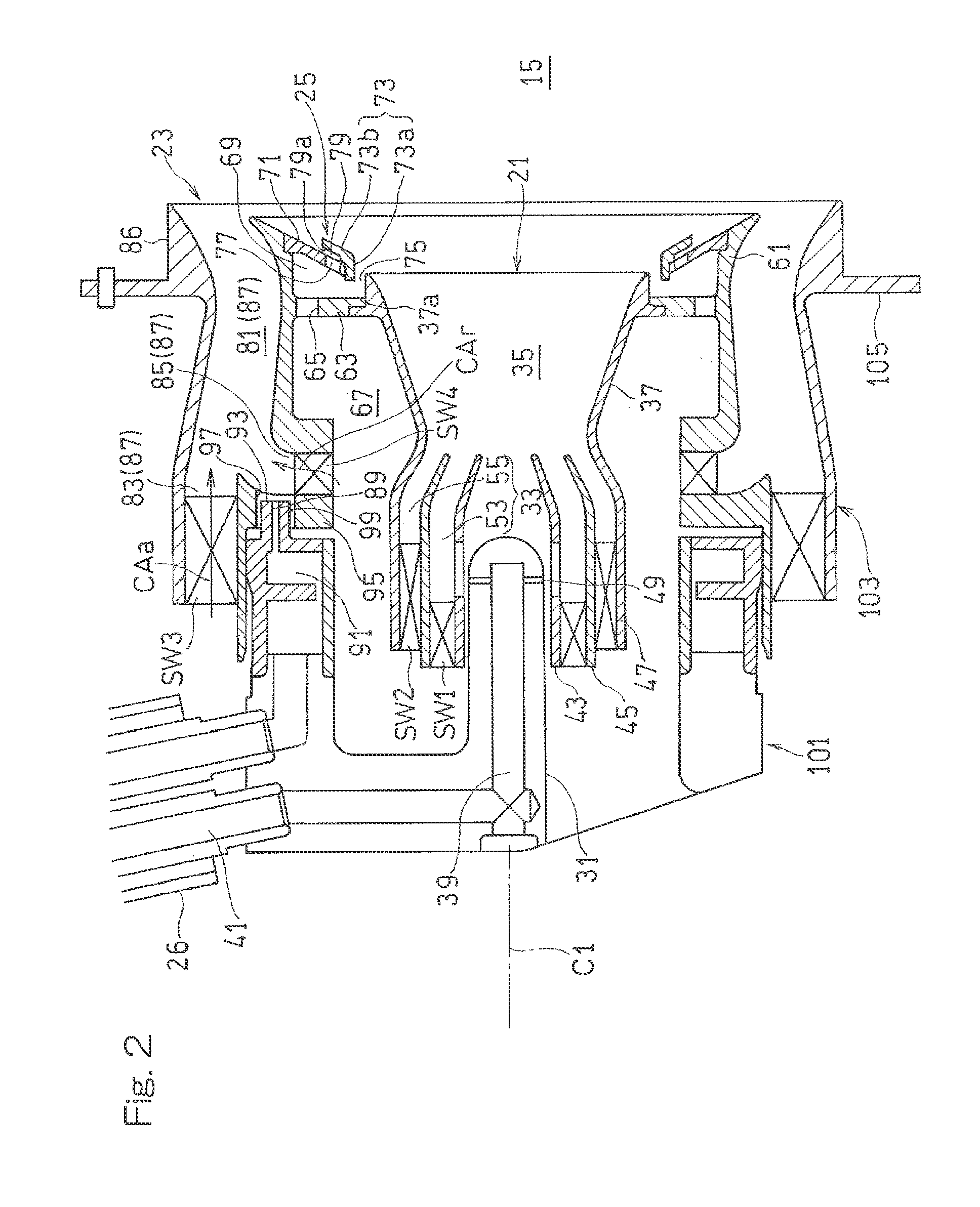
[0024]Hereinafter, embodiments of the present invention will be described in detail with reference to the accompanying drawings. FIG. 1 illustrates a combustor CB for a gas turbine engine equipped with a fuel injector 1 designed in accordance with an embodiment of the present invention. The combustor CB is operable to mix fuel with a compressed air CA, fed from a compressor (not shown) of the gas turbine engine, and burn the resultant air-fuel mixture to produce high temperature and high pressure combustion gases, which are in turn fed to a turbine to drive this turbine.

[0025]The combustor CB is of an annular configuration and includes an annular outer casing 3 and an inner casing 5 located radially inner side of the outer casing 3, which casings 3 and 4 are positioned in a coaxial relation with an engine rotary longitudinal axis C so as to form a combustor housing 7 having an annular inner space defined therein. The annular inner space of the combustor housing 7 accommodates therei...


PUM


Abstract

A fuel injector includes a pilot fuel injector, configured to inject the fuel into a combustion chamber, and a main fuel injector provided coaxially with the pilot fuel injector so as to surround the pilot fuel injector and configured to have a main flow path to generate a premixed air-fuel mixture. The main flow path includes an outer main air passage located radially outwardly and configured to supply a compressed air in an axial direction into an annular premixed air-fuel mixture passage, an inner main air passage located radially inwardly and configured to supply the compressed air into the premixed air-fuel mixture passage from a radially inner side. The injector further includes a main fuel injection port to inject the fuel from an axially upstream side into the inner main air passage.

Description

CROSS REFERENCE TO THE RELATED APPLICATIONS[0001]This application claims priority to Japanese patent application No. 2012-129682, filed Jun. 7, 2012, the disclosure of which is incorporated by reference in its entirety into this application.BACKGROUND OF THE INVENTION[0002]1. Field of the Invention[0003]The present invention relates to a fuel injector for use in, for example, a gas turbine engine and, more particularly, to the fuel injector equipped with a complex fuel injector comprised of a plurality of fuel nozzles.[0004]2. Description of Related Art[0005]In recent years, in consideration of the environment, there is a need for a reduction of emissions such as NOx (nitrogen oxide) emitted from gas turbine engines. A fuel injector of the conventional aircraft gas turbine combustor is of a diffusive combustion type, and since in the diffusion combustion, the burning reaction takes place based on the stoichiometric mixture ratio, the flame temperature tends to increase. Considering ...

Claims


Application Information

Patent Timeline
Patent Type & Authority Applications(United States)
IPC IPC(8): F02M23/12
CPCF02M23/12Y02T10/12F23R3/14F23R3/286F23R3/343
Inventor MATSUYAMA, RYUSUKEKOBAYASHI, MASAYOSHIHORIKAWA, ATSUSHIFUJIWARA, HITOSHI
Owner KAWASAKI HEAVY IND LTD
Why Eureka
Try Eureka