
Combustion device to provide a controlled heat flux environment

a combustion device and heat flux technology, applied in the direction of combustion types, machines/engines, lighting and heating apparatus, etc., can solve the problems of high initial cost of the rocket motor, the amount of land required, and the cost of the test of this type of rocket motor

Active Publication Date: 2013-05-28
THE GOVERNMENT OF THE UNITED STATES OF AMERICA AS REPRESENTED BY THE SEC OF THE NAVY NAVAL RES LAB WASHINGTON
View PDF15 Cites 0 Cited by
  • Summary
  • Abstract
  • Description
  • Claims
  • Application Information

AI Technical Summary

Benefits of technology

The system provides a cost-effective and controlled means to assess the response of energetic materials to heat flux, enabling more accurate computational modeling and reducing the need for expensive full-scale tests by simulating the thermal penetration experienced by full-scale articles in a controlled and tunable manner.

Problems solved by technology

A test of this type can be very expensive for rocket motors greater than 11 inches in diameter as it requires the use of three full-sized, production assets or rocket motors in their shipping and storage configuration.
The initial cost of the rocket motor, the potential hazards associated with conducting the test, and the amount of land required for a test site are some of the difficulties in performing an external fire test on a solid rocket motor.
For large-scale rocket motors, it is highly likely that performing a full-scale fuel-fire test will be cost prohibitive.
Furthermore, the physical nature of a fuel-fire is very difficult to quantify and measure.
This type of full-scale fuel fire testing is difficult to perform because it requires the use of a full-scale test specimen and large specialized facilities, both of which can be extremely expensive.
The full-scale test is capable of providing the necessary thermal stimulus, but it lacks sufficient instrumentation to quantify the stimulus for use in present day computational models.
Technology is not currently available to provide the necessary resolution of measured heat flux level or provides a sufficient level of control for the application of constant thermal boundary conditions into a small-scale / smaller than full-scale test specimen for the purpose of observing the resulting response of the energetic material.

Method used


Image

  • Combustion device to provide a controlled heat flux environment
  • Combustion device to provide a controlled heat flux environment
  • Combustion device to provide a controlled heat flux environment

Examples


Embodiment Construction

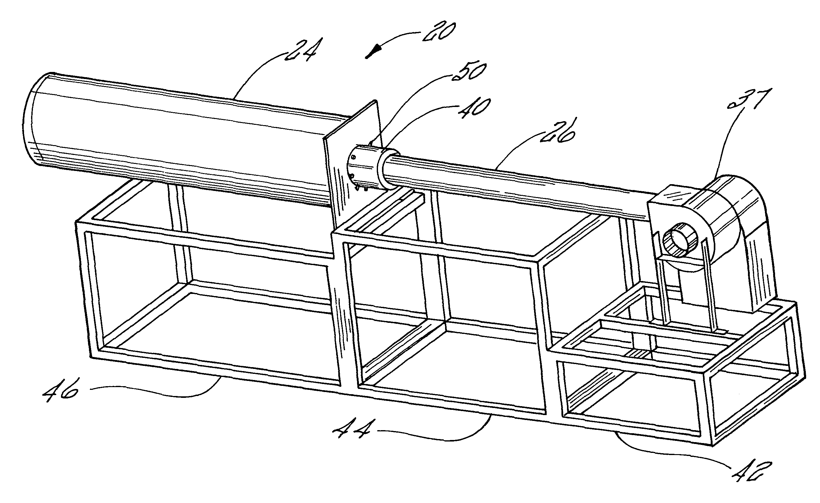
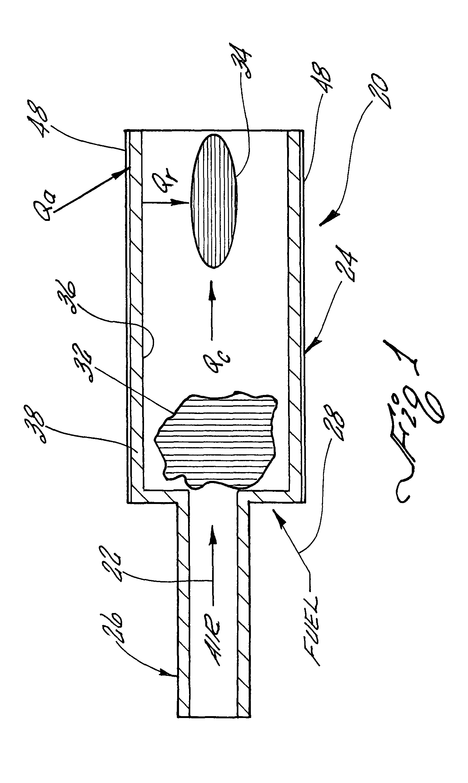
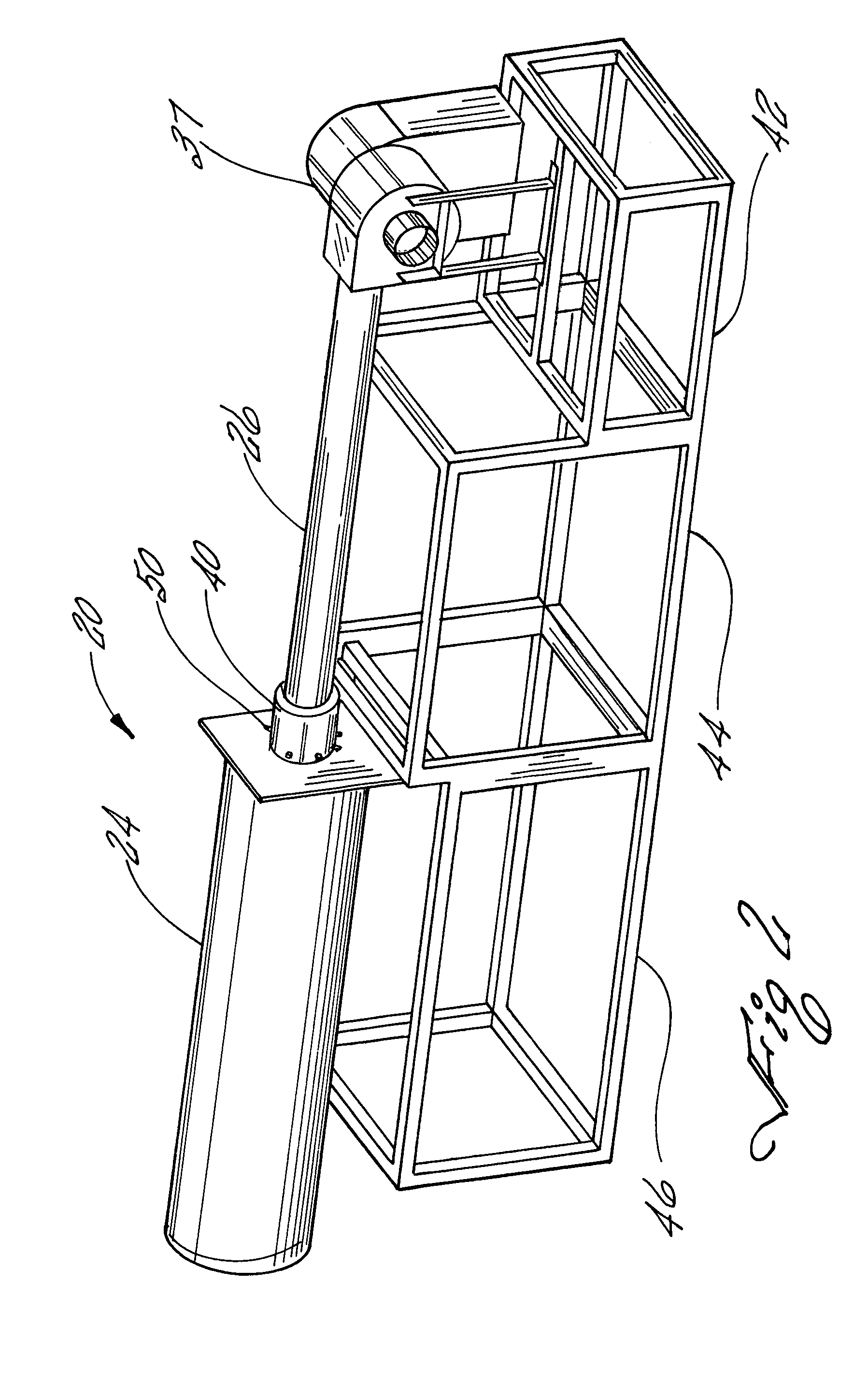
[0014]Referring to FIG. 1, FIG. 1 illustrates the main elements of the combustion device 20 for providing a controlled heat flux environment. Combustion device 20 operates as a fast cook-off response device for insensitive munitions testing. Air, which is represented by arrow 22, enters the combustion chamber 24 via an air duct 26 at a flow rate which is determined by the required operating heat flux conditions. Fuel, which is represented by arrow 28, is injected at a location in the air duct 26, such that the fuel 28 can mix with the air 22 to provide a flammable mixture within combustion chamber 24. This mixture is then ignited in the combustion chamber 24 at which time the fuel is consumed in a reaction region 32 within combustion chamber 24, generating high-temperature gas products.

[0015]As shown in FIG. 1, the combustion chamber 24 has an inside diameter which is larger than the inside diameter of air duct 26. The change in area from the smaller air duct 26 to the larger combus...


PUM


Abstract

A propane fueled combustor for providing a controlled heat flux environment of twenty to two hundred kilowatts per square meter. The combustor has the capability of generating a repeatable and quantifiable environment in which to evaluate a response of an energetic material to a fast cook off hazard, such as a liquid fuel fire.

Description

BACKGROUND OF THE INVENTION[0001]1. Field of the Invention[0002]The present invention relates generally to hazards classification of energetic materials and other explosive ordinance. More particularly, the present invention relates to a propane fueled combustion device which provides a controlled heat flux environment for hazardous classification of an ordinance system.[0003]2. Description of the Prior Art[0004]In the United States, all ordnance must be hazard classified. Hazards classification of an energetic material (which are used in all ordnance systems) requires a number of tests to determine the type of reaction and level of reaction violence for various potential accident scenarios in transport and storage situations. These tests include shock initiation, sympathetic detonation, and external fuel-fires which are referred to as cook-off tests. Both shock initiation and sympathetic detonation tests have small-scale analog tests that allow for alternative options to expensive ...

Claims


Application Information

Patent Timeline
Patent Type & Authority Patents(United States)
IPC IPC(8): F02B45/08
CPCF23D21/005F23D91/02
Inventor WILSON, KENNETH JAYLAKER, TRAVIS SHANEWASHBURN, EPHRAIM BERKATWOOD, ALICE IRENE
Owner THE GOVERNMENT OF THE UNITED STATES OF AMERICA AS REPRESENTED BY THE SEC OF THE NAVY NAVAL RES LAB WASHINGTON
Learn More