Fluorescence flow cytometry
a flow cytometer and flow cytometer technology, applied in the field of fluorescence flow cytometers, can solve the problems of inconvenient use, high equipment cost, and inconvenient use, and achieve the effect of minimizing autofluorescen
- Summary
- Abstract
- Description
- Claims
- Application Information
AI Technical Summary
Benefits of technology
Problems solved by technology
Method used
Image
Examples
embodiment 100
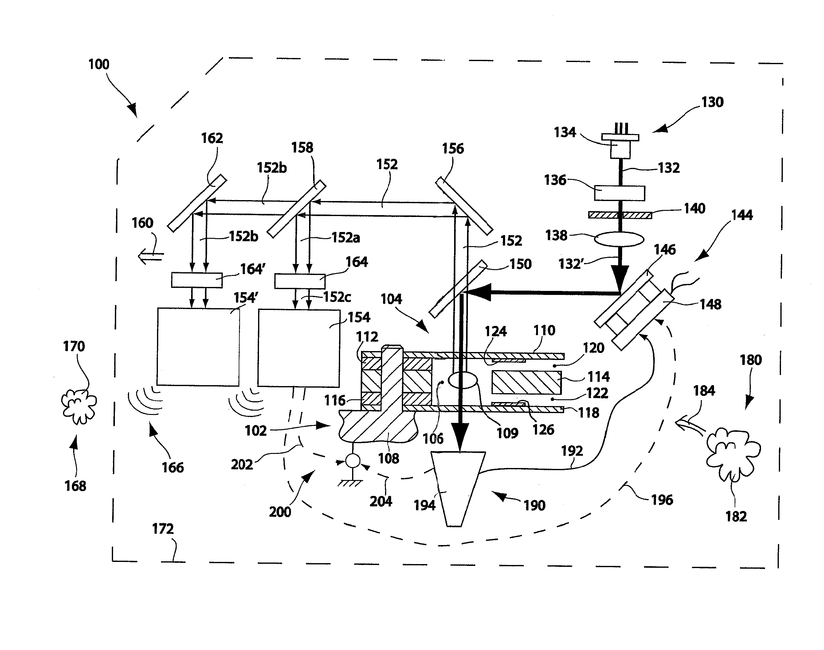
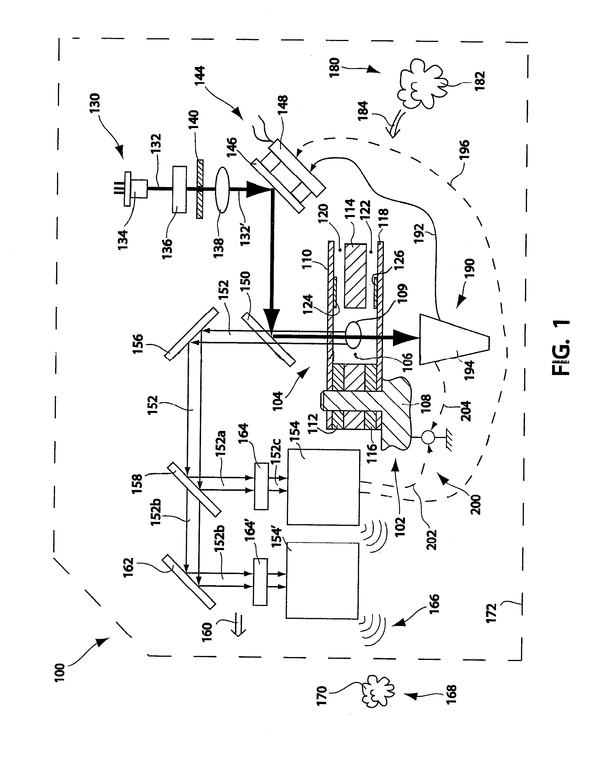
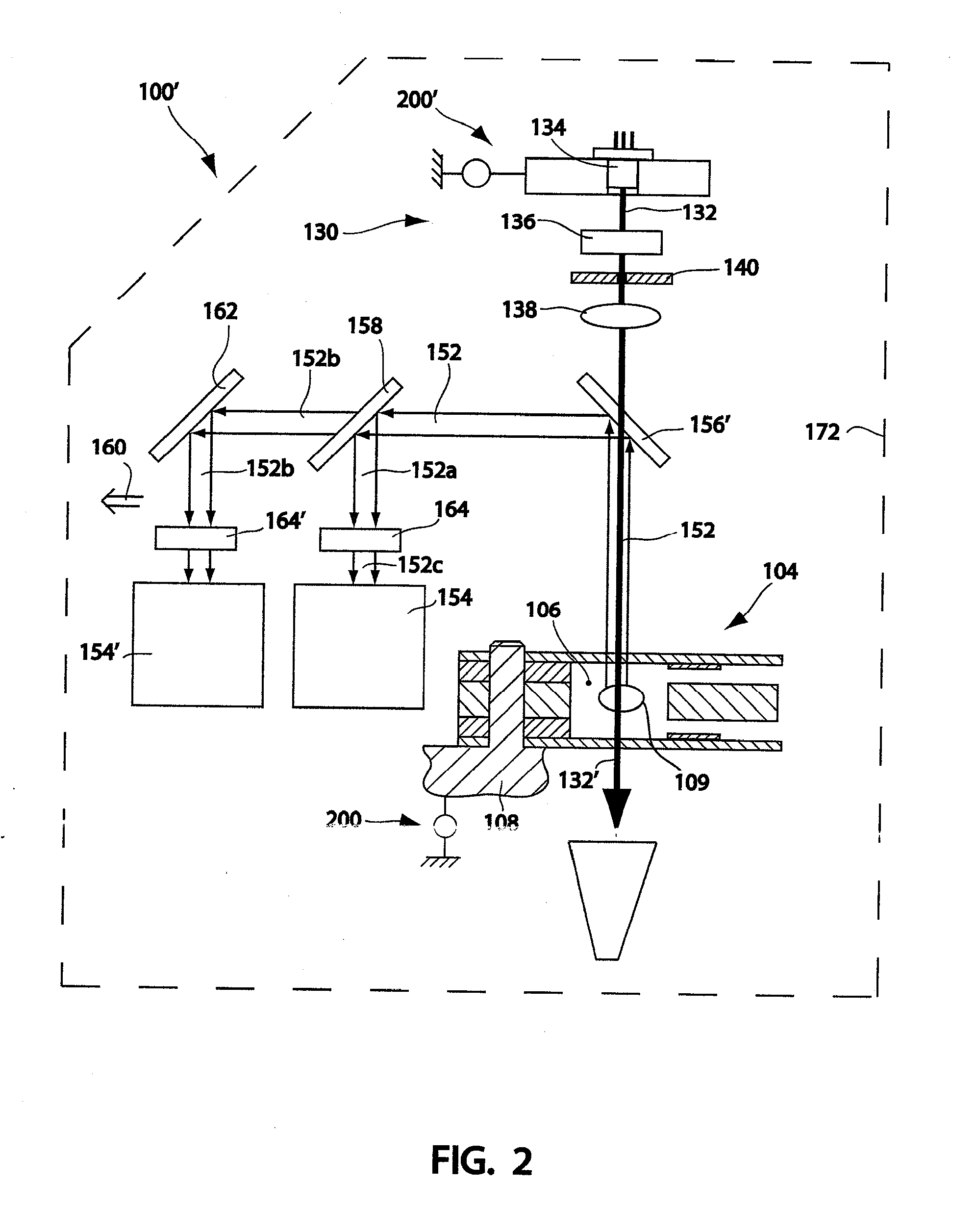
[0049]Importantly, embodiment 100′ in FIG. 2 illustrates an X-Y adjustment system 200′ adapted to displace the stimulation radiation source 130 relative to the aperture 106. It is also within contemplation that adjustment system 200′ may also, or alternatively, change an angle of propagation of beam 132 to avoid, or at least reduce and desirably minimize, undesired autofluorescence and thereby improve the signal-to-noise ratio obtained by interrogation device 100′. For example, one or more actuator, such as a piezo actuator or motorized link, could be disposed to rotate mounting structure for, and thereby adjust the angle of discharge of, laser 134.
[0050]Similar to embodiment 100, interrogation device 100′ may alternatively, or also, include an X-Y adjustment structure such as is generally indicated at 200. Adjustment system 200 is effective to move a cassette 104 from an initially installed position in a fine-tuning operation, and consequently move aperture 106 with respect to the ...
embodiment 210
[0051]FIG. 3 illustrates selected elements of a workable and compact packaging arrangement for an interrogation device, generally indicated at 210. Embodiment 210 desirably fits into the preferred envelope 172. Straight-shafted arrows indicate direction of propagation of radiation.
[0052]Elements of embodiment 210 in common with previously disclosed embodiments are generally identified with similar numerals. Holding structure, to hold a cassette, such as cassette 104, in an initial installed position, is generally indicated at 211. Repeated elements are indicated by subscript. In the illustrated embodiment, subscript a=1, and subscript n=4. It must be appreciated that n could be a larger number; generally controlled by available technology and corresponding elements having desired discrimination capabilities.
[0053]Of note, steering mirror 146′ is a dichroic mirror, which reflects stimulation radiation beam 132′ (downwardly as drawn), toward an interrogation aperture in an installed m...
embodiment 220
[0054]With reference now to FIG. 4, another alternative embodiment structured to apply stimulation radiation to an interrogation aperture is illustrated, and is generally indicated at 220. Again, elements of embodiment 220 in common with previously disclosed embodiments are generally identified with similar numerals. Importantly, stimulation radiation is directed from laser assembly 222, through dichroic mirror assembly 226 to steerable mirror assembly 228, which directs stimulation radiation down into an interrogation aperture of a microfluidic device, such as cassette 104. Emission radiation propagating up from the interrogation aperture is reflected from the mirror element of assembly 228 through the dichroic element of assembly 226 and toward the path-folding mirror 156 for detection by the photodetectors 154a-d. A motor and cam assembly 230 may be provided to clamp a microfluidic device 104 in engagement with indexing structure.
[0055]With reference now to FIG. 5, which is illus...
PUM
| Property | Measurement | Unit |
|---|---|---|
| volumetric size | aaaaa | aaaaa |
| volumetric size | aaaaa | aaaaa |
| volumetric size | aaaaa | aaaaa |
Abstract
Description
Claims
Application Information
 - R&D
- Intellectual Property
- Life Sciences
- Materials
- Tech Scout
- Unparalleled Data Quality
- Higher Quality Content
- 60% Fewer Hallucinations
Browse by: Latest US Patents, China's latest patents, Technical Efficacy Thesaurus, Application Domain, Technology Topic, Popular Technical Reports.
© 2025 PatSnap. All rights reserved.Legal|Privacy policy|Modern Slavery Act Transparency Statement|Sitemap|About US| Contact US: help@patsnap.com


