Optical apparatus

a technology of optical apparatus and optical tube, which is applied in the field of optical tube, can solve the problems of difficult optical design to favorably correct aberration of objective and other optical systems, low transmittance in the ultraviolet region, and limit the selection of vitreous materials, etc., and achieves excellent operability and system flexibility, the effect of minimizing the autofluorescence produced

Inactive Publication Date: 2005-10-20
OLYMPUS CORP
View PDF20 Cites 16 Cited by
  • Summary
  • Abstract
  • Description
  • Claims
  • Application Information

AI Technical Summary

Benefits of technology

[0035] The present invention was made in view of the above-described circumstances of the prior art. An object of the present invention is to provide a fluorescence observation optical apparatus including a fluorescence microscope and a stereoscopic microscope allowing fluorescence observation. The fluorescence observation optical apparatus is designed to minimize autofluorescence produced from glass in an observation optical system by excitation light from a fluorescence illumination optical system and to prevent excitation light from entering the observation optical system as stray light or leakage light, thereby allowing observation with high contrast. Further, illuminating light from the fluorescence illumination optical system is utilized efficiently to allow observation of a bright fluorescence image. Moreover, the fluorescence observation optical apparatus is excellent in operability and system flexibility.

Problems solved by technology

Therefore, there is a limitation on the selection of vitreous materials, and it is difficult in terms of optical design to favorably correct aberration of the objective and other optical systems for fluorescence observation.
Moreover, the transmittance in the ultraviolet region is low.
However, because the illumination area of the fluorescence illumination optical system does not change in association with the change of the observation area caused by the magnification changing operation of the observation optical system, operability is very bad.
Moreover, because a light guide fiber is used in the illumination optical system, the excitation light illumination efficiency is low.
Accordingly, the fluorescence image for observation is unfavorably dark.
Accordingly, operability is not good.
As a result, the contrast of the observation image is partially degraded.
Therefore, the fluorescence illumination apparatus cannot be used in combination with a stereoscopic microscope that has heretofore been used.
Accordingly, the apparatus is inferior in compatibility and system flexibility.
The surgical microscope is unsuitable for fluorescence observation and different from the stereoscopic microscope allowing fluorescence observation in use application and also in performance required of the observation optical system and the illumination optical system.

Method used


Image

  • Optical apparatus
  • Optical apparatus
  • Optical apparatus

Examples


example 1

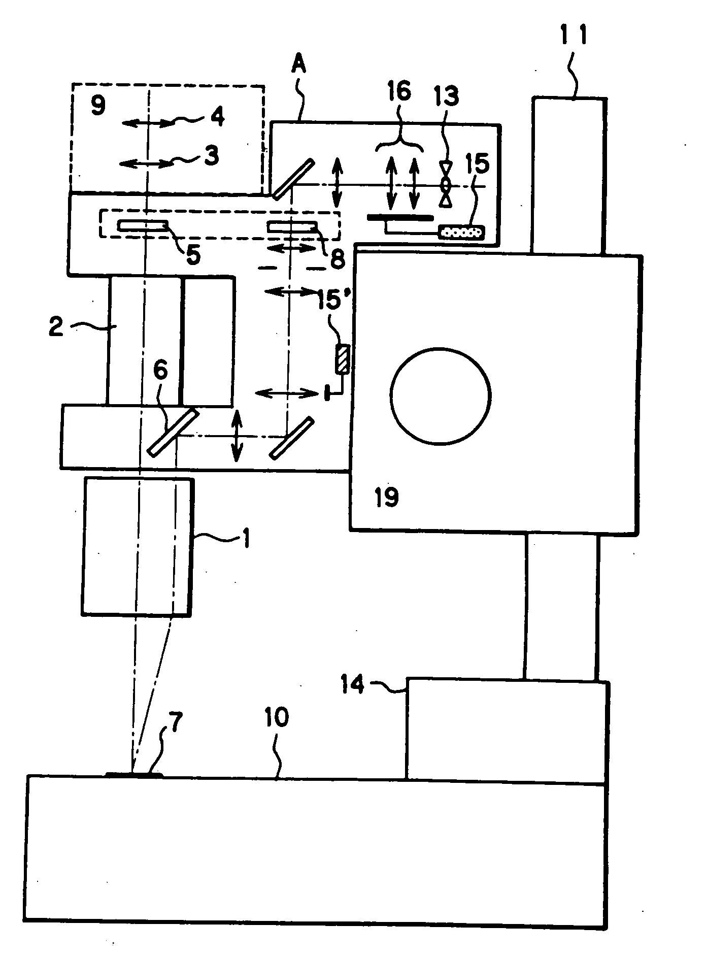
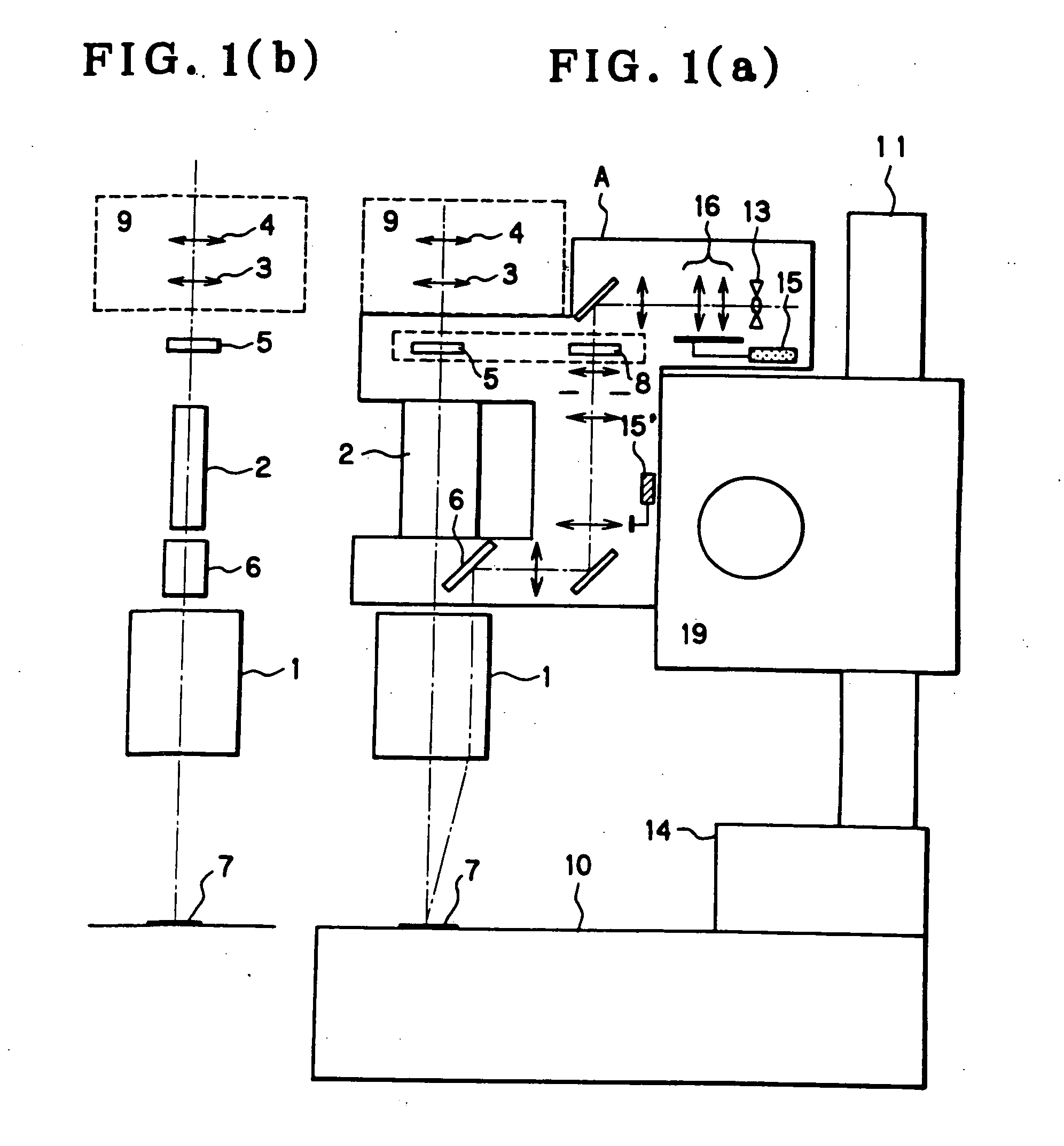
[0179] The arrangement of Example 1 of the optical apparatus according to the present invention is shown in FIG. 10. Part (a) of FIG. 10 is a front view of the optical apparatus, which shows only an optical system for viewing fluorescent light. Part (b) of FIG. 10 is a side view of the entire optical apparatus. Part (a) of FIG. 11 is a side view showing the arrangement of the optical apparatus according to Example 1 when a fluorescence illumination apparatus is not used. Part (b) of FIG. 11 shows the arrangement of a frame socket used in the optical apparatus according to Example 1.

[0180] The optical apparatus according to Example 1 has a frame 10, a frame socket 14, a post 11, a focusing unit 19, an observation apparatus C, and a fluorescence illumination apparatus A.

[0181] The frame 10 serves as a stage for holding a sample 7 and also serves to hold the post 11 through the frame socket 14. As shown in part (b) of FIG. 11, the frame socket 14 is provided with two insertion holes ...

example 2

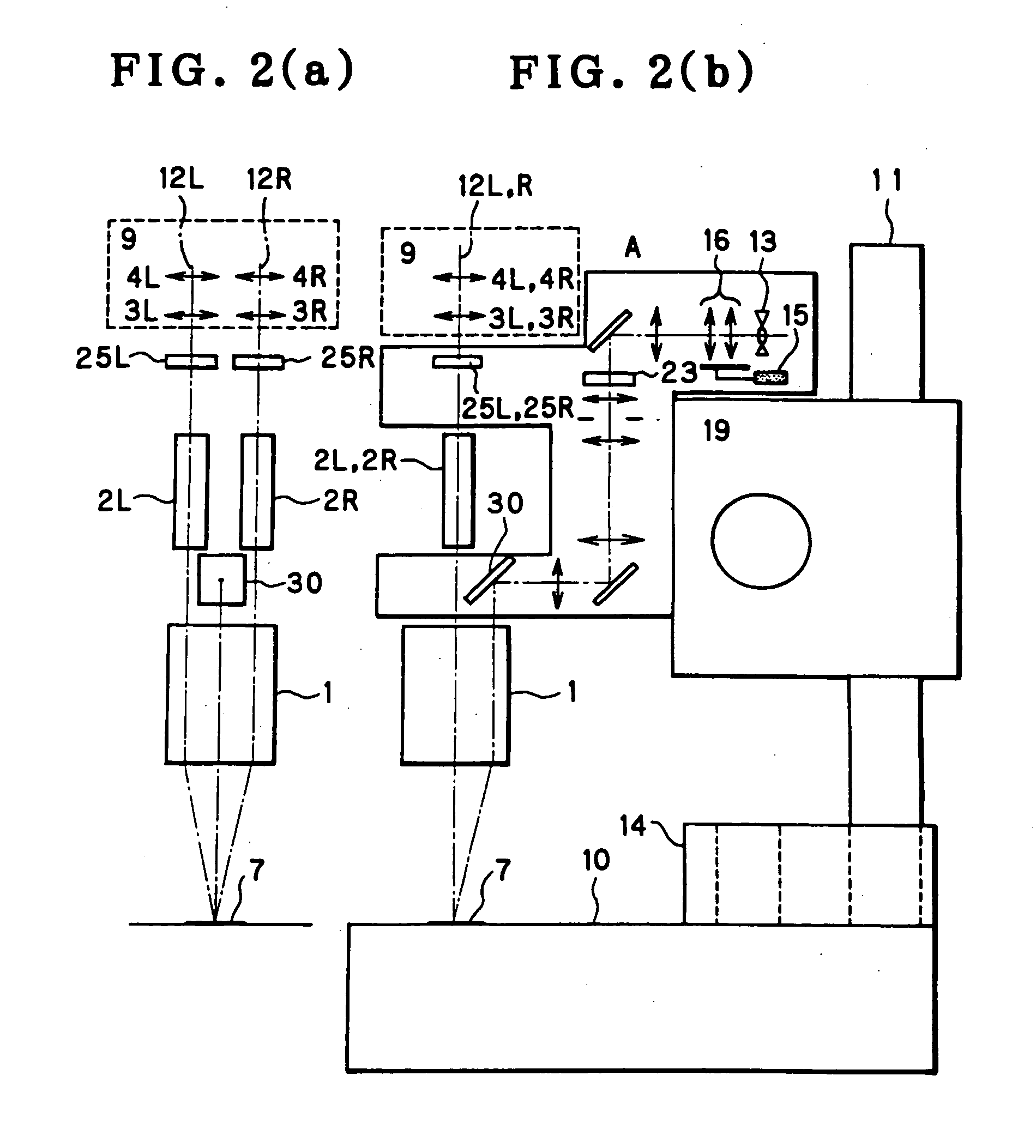
[0228] Example 2 of the optical apparatus according to the present invention is shown in FIG. 18. In the optical apparatus shown in FIG. 18, the observation optical system unit and the imaging optical system unit of the optical apparatus according to Example 1 are each formed from a pair of lens units, and the pair of lens units are placed in parallel and symmetry with respect to the optical axis of the objective. The optical apparatus is a Galilean stereoscopic microscope. It should be noted that the optical apparatus uses a fluorescence illumination apparatus A, a frame 10, a frame socket 14, a post 11 and a focusing unit 19 which have arrangements similar to those in Example 1. In the fluorescence illumination apparatus A, the movement of the collector lens unit G0 and the movement of the movable lens in the second relay lens unit G2 can be performed in the same way as in Example 1. The excitation filter 23 and the absorption filters 25L and 25R can be adapted to be interchangeab...

example 3

[0241] Example 3 of the optical apparatus according to the present invention is shown in FIG. 21. In the optical apparatus shown in FIG. 21, the objective, the observation optical system unit and the imaging optical system unit of the optical apparatus according to Example 1 are each formed from a pair of lens units. The pair of lens units of each of these components are placed at a tilt to an axis normal to the sample surface and in symmetry with respect to the axis. Thus, the optical apparatus is a Greenough stereoscopic microscope. It should be noted that the optical apparatus uses a fluorescence illumination apparatus A, a frame 10, a frame socket 14, a post 11 and a focusing unit 19 which have arrangements similar to those in Example 1. In the fluorescence illumination apparatus A, the movement of the collector lens unit G0 and the movement of the variable lens in the second relay lens unit G2 can be performed in the same way as in Example 1. The excitation filter 8 and the abs...


PUM


Abstract

An optical apparatus minimizes autofluorescence and stray light as well as leakage of excitation light and efficiently utilizes illuminating light from a fluorescence illumination optical system to allow observation of a bright fluorescence image. An observation apparatus has an objective, an observation optical system unit including a variable magnification optical system, and an imaging optical system unit including an imaging lens and an eyepiece. A fluorescence illumination apparatus, which is provided separately, is removably attached to the observation apparatus. The fluorescence illumination apparatus has a light source, a collector lens unit, and a reflecting member placed between the objective and the observation optical system unit at a position displaced from the optical axis of the objective to make light from the light source incident on the objective. An excitation filter is provided between the light source and the reflecting member. An optical member for selectively transmitting fluorescent light emitted from a sample is placed between the objective and the observation optical system unit.

Description

[0001] This application claims benefit of Japanese Application No. Hei11-344786 filed in Japan on Dec. 3, 1999, the contents of which are incorporated by this reference. BACKGROUND OF THE INVENTION [0002] The present invention relates to optical apparatus and, more particularly, to fluorescence observation optical apparatus including a fluorescence microscope and a stereoscopic microscope allowing fluorescence observation. [0003] In recent years, fluorescence observation under a fluorescence microscope and a stereoscopic microscope has been widely used not only in micro observation but also in macro observation at low magnification. In particular, fluorescence proteins such as GFP (Green Fluorescence Protein), CFP (Cyan Fluorescence Protein) and YFP (Yellow Fluorescence Protein) have advantages in comparison to conventional fluorescent dyes. That is, such fluorescence proteins show a comparatively low toxicity to cells, suffer less fading and provide brighter fluorescence. According...

Claims


Application Information

Patent Timeline
Patent Type & Authority Applications(United States)
IPC IPC(8): G02B21/06G02B21/16G02B21/22G02B21/24
CPCG02B21/06G02B21/22G02B21/16
Inventor KAWASAKI, KENJINISHIWAKI, DAISUKESHIMIZU, KEIJI
Owner OLYMPUS CORP
Why Eureka
Try Eureka