
System for imaging lesions aligning tissue surfaces

a tissue surface and imaging technology, applied in the field of medical diagnostic devices and methods, can solve the problems of increasing the risk of developing melanoma, difficult treatment, death, etc., and achieve the effects of low cost, quick test performance, and convenient us

Active Publication Date: 2019-01-01
ORLUCENT INC
View PDF42 Cites 3 Cited by
  • Summary
  • Abstract
  • Description
  • Claims
  • Application Information

AI Technical Summary

Benefits of technology

[0057]A need exists for improved systems and methods having desirable diagnostic features. Such desirable diagnostic features may include one or more of the following: is minimally invasive or non invasive; permits early stage disease detection; permits early body response to a new antigen; permits early body response to a foreign antigen, monitors disease development and progression; investigates the macro environment of the diseased cell and / or tissue as indication of presence of disease; is easy to use, low cost, provides a quick test to perform; can be performed by someone other than the physician; operates independent of skin color or ethnicity; provides immediate test results, provides consistency of results, works for a wide range of lesion types and body locations; is minimally dependent on human interpretation; is a simple test—minimal training necessary; provides automated or machine-assisted medical documentation, such as photographs or quantified test metrics; provides automated or machine-assisted electronic medical record keeping, such as machine readable codes on samples and files that directly tie to patient, doctor and date; operates independent of visual cues such as, color, shape and size; can identify melanoma in amelanotic skin lesion; and / or can identify melanoma in small lesions, less than 5 mm.
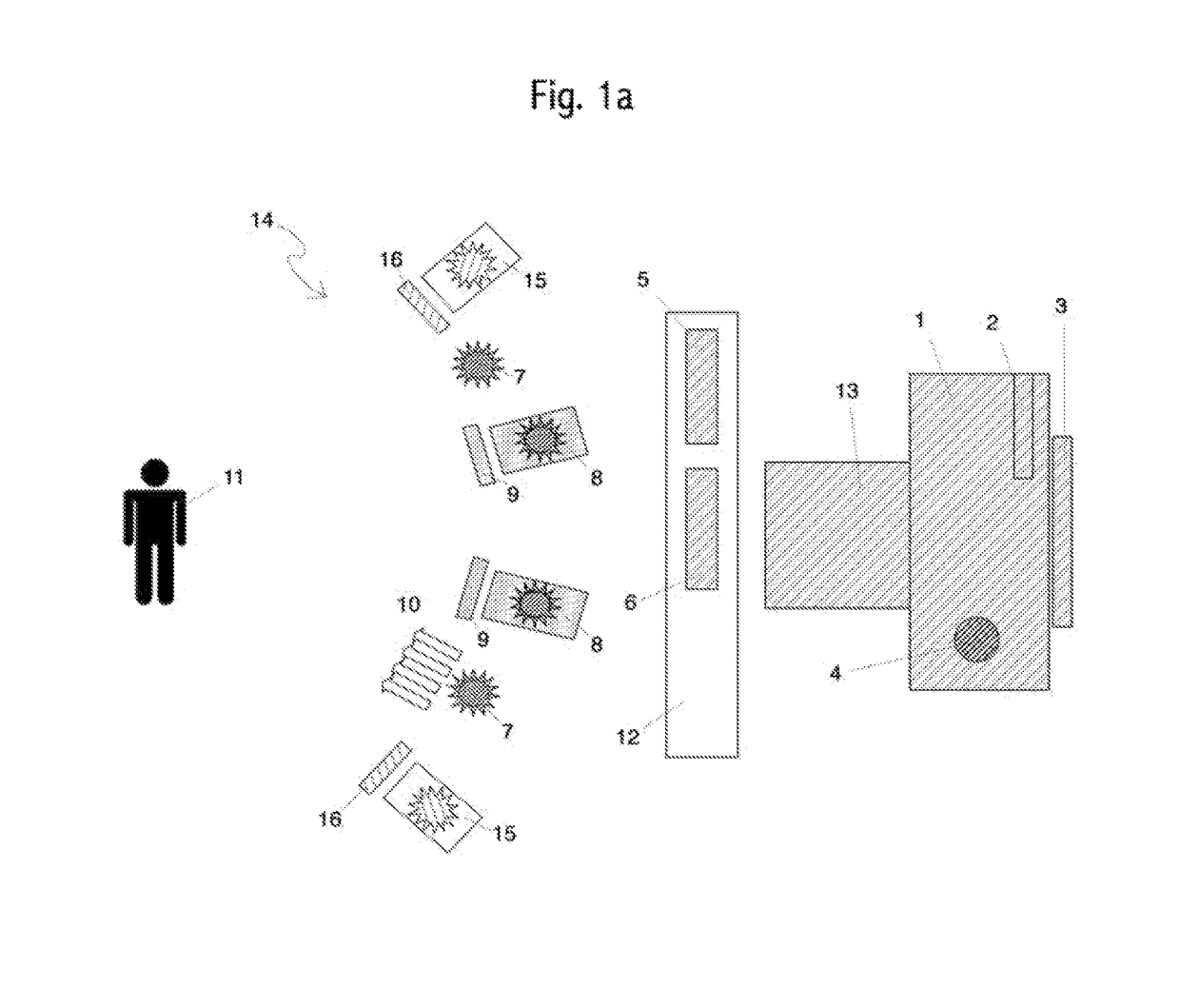
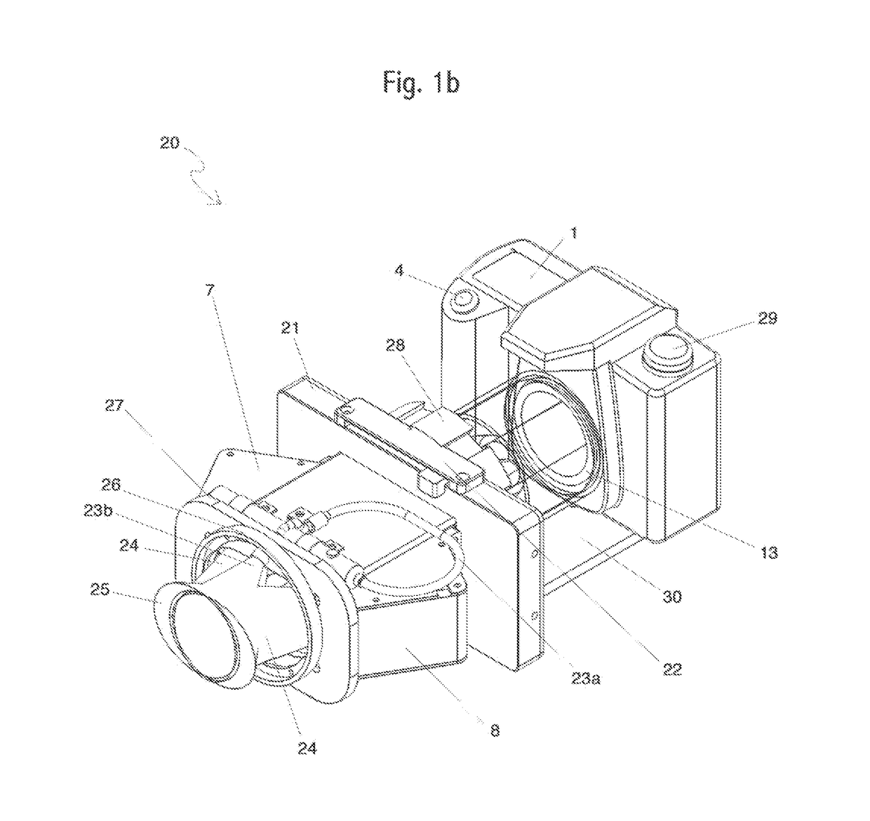
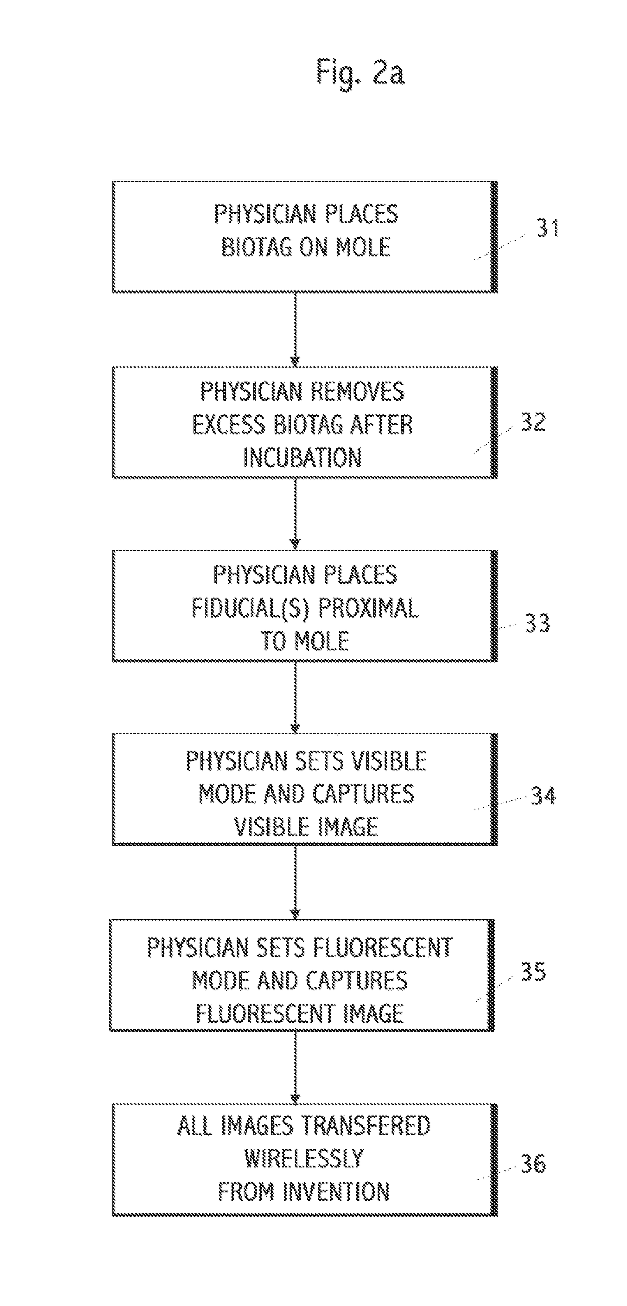
[0066]TABLE 1Use of a consumer, integrated camera as a starting point for the method of manufacturing thecamera, for low cost, ability to be hand held, compactness, portability, and reliability. Anindustrial camera can also be used.Use of the camera's built-in autofocus capabilities, and the autofocus software may be changedor updated.Use of the camera's autofocus in the infrared range.Use of the lens that comes with the camera, either integrated with the body or aninterchangeable lens designed for use with the camera, preferably a macro-lens.Two, three, or four light sources—one visible light for skin, one excitation light for cancerdetection, one emission light for autofocus (option), and one for 3D and surface roughnessimage capture and analysis (option).Dual, dynamically selectable light filters, one band pass for visible, one for IR detection.Optionally, a single filter with two pass-bands and one-stop band may be used.Taking two photographs in two different wavelength bands using the same camera, optics,controls, and image storage.Methods to align display and view the two above photographs.Use of a biotag in conjunction with the other features of this invention.Use of a multi-function fiducial.Use of an eight-function fiducial (exposure / brightness, calibration, focus, patient orientation,patient id, linear metric, alignment of multiple images, number of mole on patient) optionalinformation about the diagnostic procedure.Use of machine-readable codes (1D, 2D, text) on the fiducial, with machine printed on demand,pre-printed, hand-written areas, or a hybrid of these manufacturing attributes.Use of both visible fiducial features and emission spectra features on the same or separatefiducial.Changing the autofocus firmware on the camera to handle focusing in the infrared light band.Removing the infrared blocking filter originally placed in the primary optical path in the cameraduring original manufacturing.Removing the infrared blocking filter originally placed in the focusing optical path in the cameraduring original manufacturing.Removing the RGB filter on top of the infrared filter optional. Removing the RGB filter will givebetter fluorescent sensitivity (about 15% more light) and higher pixel count in fluorescent butvisible image will be black and white and not color.Use of an engineered diffuser for one or two light sources.Integrating all light sources and filters into a single, integrated camera that operates without anexternal computer or the need for external connectivity or power.
[0068]This invention overcomes all of these deficiencies yet still maintains the fundamental benefits of a low-cost, compact, portable, handheld, reliable camera. Systems and methods provided herein may advantageously include removing one, two or three filters originally manufactured in the camera, modifying the auto-focus, adding light sources, adding dynamically selectable filters, and the use of complex fiducials to enable auto-exposure, auto-focus, and image alignment. When imaging light below 700 or 710 or 720 or 730 or 740 or 750 nm the filter many not need to be removed.
[0085]In some embodiments, the wavelength for emission from the label is in the range of the near infrared. Such labels include, without limitation, Alexa dyes such as Alexa 647, Alexa 680, Alexa 700 and Cyanine dyes such as Cy 5, Cy5.5. Cy7 Characteristics considered for label selection include its light absorption, and a minimization of autofluorescence from the body surface to be measured. The probe will respond to florescent illumination of a specific wavelength and will then emit light at a different wavelength.
[0113]Polymeric MNs can provide biocompatibility, biodegradability, strength, toughness, and optical clarity. To accurately produce the micro-scale dimensions of polymer MNs, a variety of mould-based techniques, such as casting, hot embossing, injection molding, and investment molding may be used, e.g. beveled-tip, chisel-tip, and tapered-cone polydimethylsiloxane (PDMS) molds. Polymeric materials of interest for fabrication include without limitation; poly (methylmetha-acrylate) (PMMA), poly-L-lactic acid (PLA), poly-glycolic acid (PGA), and poly-lactic-co-glycolic acid (PLGA), cyclic-olefin copolymer, poly (vinyl pyrrolidone), and sodium carboxymethyl cellulose. Sugars have also been used to fabricate the MNs, such as galactose, maltose, aliginate, chitosan, and dextrin. Materials may be cross-linked through ion exchange, photo-polymerization, and the like.

Problems solved by technology

One is at increased risk of developing melanoma if there is a family history of melanoma in one or more of your first-degree relatives (parent, brother or sister, or child).
If it is recognized and treated early it is almost always curable, but if it is not, the cancer can advance and spread to other parts of the body, where it becomes hard to treat and can be fatal.
While it is not the most common of the skin cancers, it causes the most deaths.
This type of melanoma typically takes many years to develop.
A tendency to mistake the early signs of acral lentiginous melanoma for bruises or injuries to the palms, soles, or nailbeds may further delay diagnosis.
As melanoma progresses, it becomes increasingly more devastating and deadly.
However, changes in size, shape, or color of an existing mole or the appearance of a new mole is not always conclusive of presence of melanoma in a mole.
One trigger is an insufficient nutrient supply resulting in hypoxic cells.
Human malignant melanoma is a highly metastatic tumor with poor prognosis and high resistance to treatment.
Cells accumulate genetic changes and become abnormal.
Often this environment may be difficult to study, especially if the tumor is embedded deep in a tissue.
Current technology has weaknesses in all or some of the above areas.
This arrangement is either impossible to hand hold, is too cumbersome to realistically handhold, or is difficult to consistently place in the correct position.
However, arrangement fails for some lesion locations, such as on the side of a patient's nose where the light baffle will not block the ambient or stray light.

Method used


Image

  • System for imaging lesions aligning tissue surfaces
  • System for imaging lesions aligning tissue surfaces
  • System for imaging lesions aligning tissue surfaces

Examples


Embodiment Construction

[0139]While various embodiments of the invention have been shown and described herein, it will be obvious to those skilled in the art that such embodiments are provided by way of example only. Numerous variations, changes, and substitutions may occur to those skilled in the art without departing from the invention. It should be understood that various alternatives to the embodiments of the invention described herein may be employed.

[0140]In one aspect, systems, compositions and methods are provided for imaging of cavity and / or tissue lesions. Various aspects described herein can be applied to any of the particular applications set forth below, alone or in combination, or for any other types of imaging systems. The embodiments described herein may be applied as a standalone system or method, or as part of an integrated medical diagnostic and / or treatment system. It shall be understood that different aspects can be appreciated individually, collectively, or in combination with each ot...


PUM

PropertyMeasurementUnit
thickaaaaaaaaaa
thickaaaaaaaaaa
diameteraaaaaaaaaa

Abstract

Methods, compositions and systems are provided for the imaging of cavity / tissue lesions, including without limitation cavity / tissue malignant lesions, e.g. cancers of the skin, mouth, colon, digestive system cervix, bladder, lung, etc.

Description

FIELD OF THE INVENTION[0001]The field of this invention is medical diagnostic devices and methods. More specifically, imaging, analysis and diagnosis of lesions aligning tissue surfaces, such as cancers of the skin, mouth, colon, digestive system cervix, bladder, lung, etc.BACKGROUND[0002]Cancer is a leading cause of death worldwide and accounted for 7.6 million deaths (around 13% of all deaths) in 2008. Melanoma is an example of a cancer aligning the skin tissue surface and used here as an example. About 10% of all people with melanoma have a family history of melanoma. One is at increased risk of developing melanoma if there is a family history of melanoma in one or more of your first-degree relatives (parent, brother or sister, or child).[0003]Melanoma is currently the sixth most common cancer in American men and the seventh most common in American women. The median age at diagnosis is between 45 and 55, although 25% of cases occur in individuals before age 40. It is the second m...

Claims


Application Information

Patent Timeline
Patent Type & Authority Patents(United States)
IPC IPC(8): A61B5/00G06T7/00H04N5/232H04N5/235G06T7/73A61B1/04G16H10/60
CPCA61B5/444A61B5/0077A61B5/0082A61B5/4887A61B5/6833G06T7/0012G06T7/74H04N5/235H04N5/23212A61B5/0071Y10T29/49716A61B1/043A61B5/0037A61B5/443G06T2207/10048G06T2207/30088G06T2207/30096H04N23/672H04N23/673H04N23/70H04N23/11
Inventor SHACHAF, CATHERINE M.SHACHAF, AMIT
Owner ORLUCENT INC
Learn More