Semiconductor device with spacers for capping air gaps and method for fabricating the same

a technology of air gap and spacer, which is applied in the direction of semiconductor devices, semiconductor/solid-state device details, electrical apparatus, etc., can solve the problems of capacitance (cb), the dielectric constant of the nitride layer is not effective in suppressing, and the oxide layer and the nitride layer do not have the characteristics of satisfying characteristics, so as to achieve the effect of stably capping air gaps and improving the margin of a subsequent process

Inactive Publication Date: 2013-12-12
SK HYNIX INC
View PDF8 Cites 23 Cited by
  • Summary
  • Abstract
  • Description
  • Claims
  • Application Information

AI Technical Summary

Benefits of technology

[0008]Exemplary embodiments of the present invention are directed to a semiconductor device that may improve t...

Problems solved by technology

The oxide layer and the nitride layer, however, do not have a dielectric constant to satisfy the characteristics of the semiconductor devices in which patterns and lines are becoming finer and finer.
Since the silicon nitride layer has a high dielectric constant, the silicon nitride layer is not effective in suppressing the parasitic capacitance (Cb) between the bit line and the storage node contact (SNC).
However, if the top ...

Method used


Image

  • Semiconductor device with spacers for capping air gaps and method for fabricating the same
  • Semiconductor device with spacers for capping air gaps and method for fabricating the same
  • Semiconductor device with spacers for capping air gaps and method for fabricating the same

Examples


Embodiment Construction

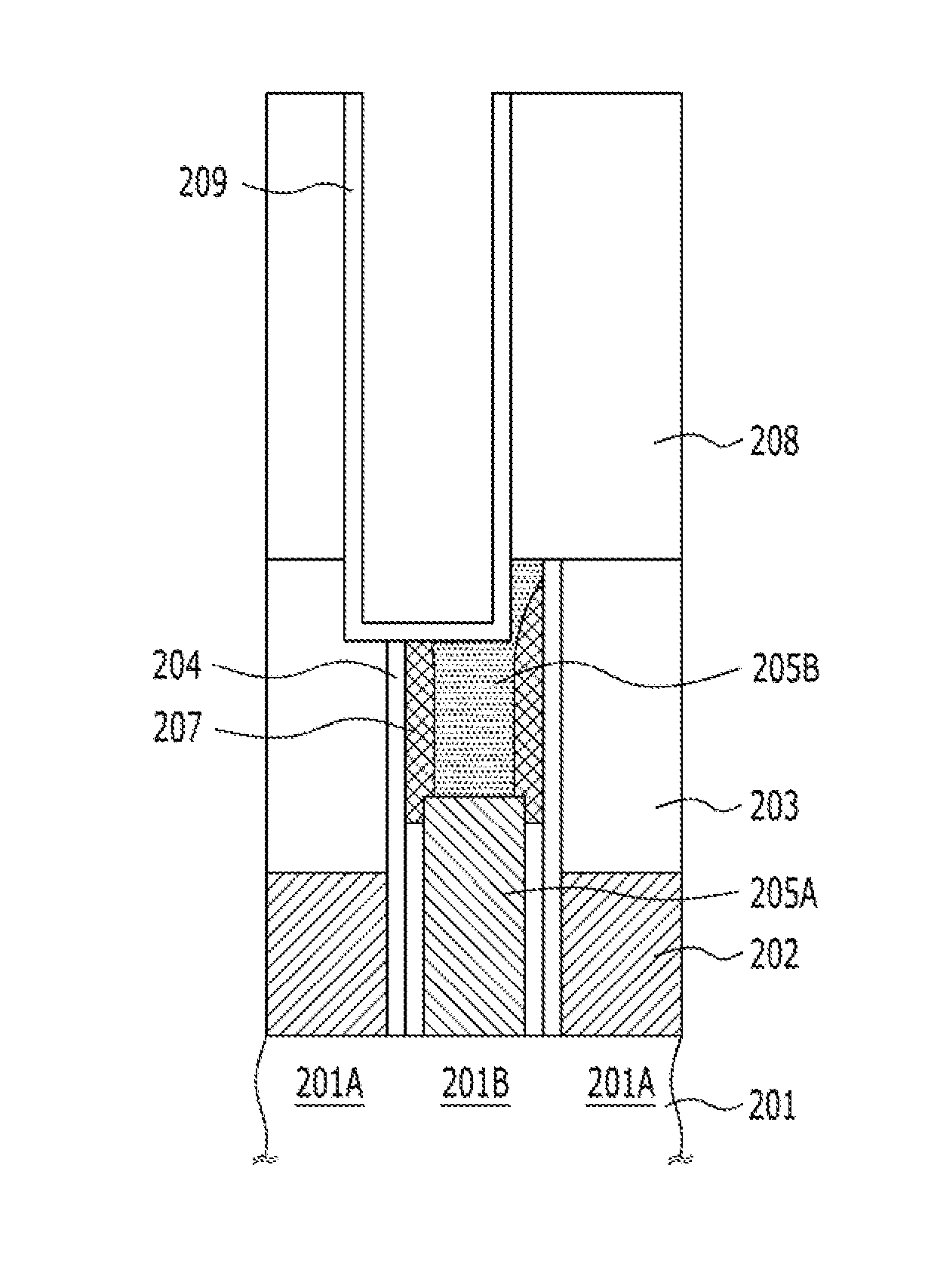
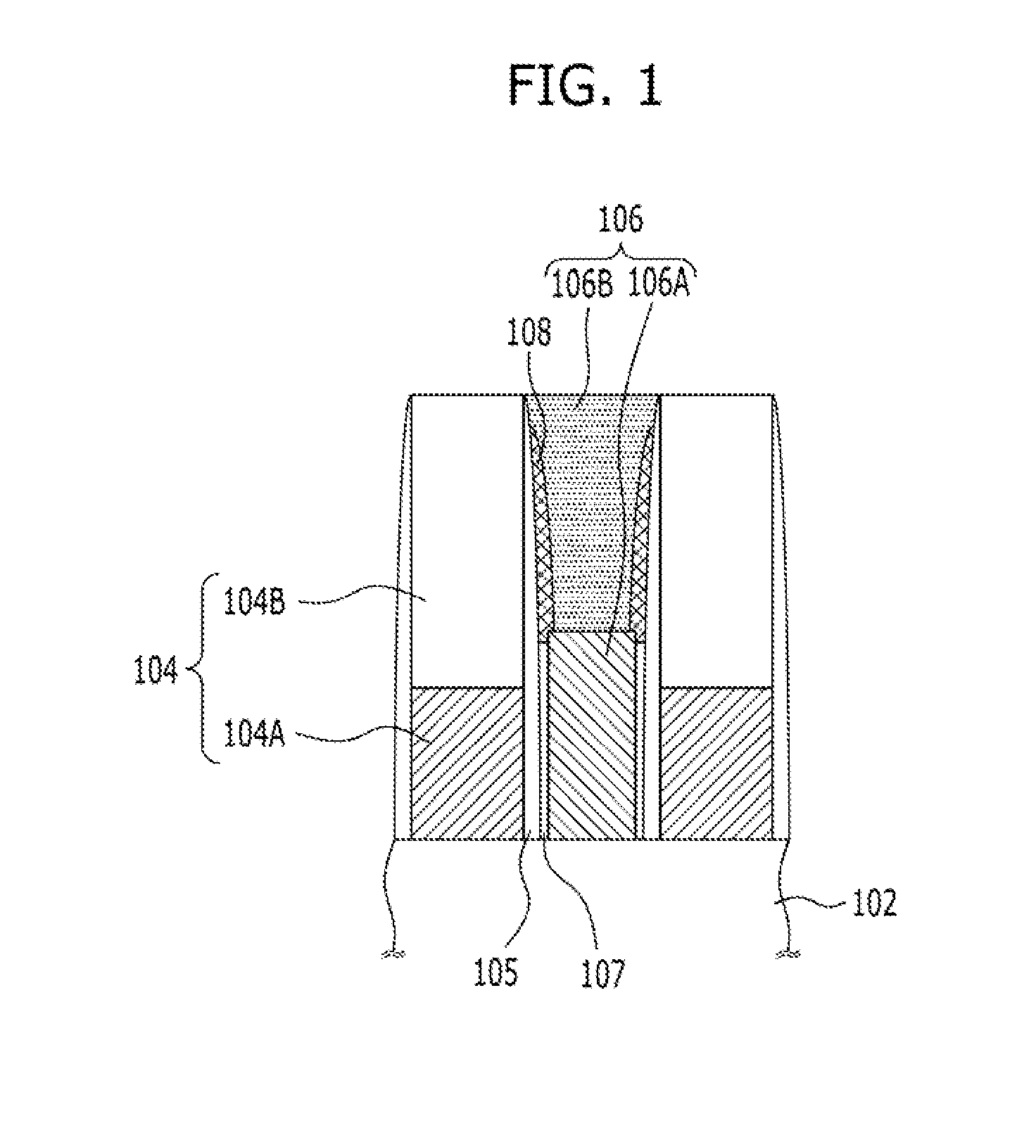
[0016]Exemplary embodiments of the present invention will be described below in more detail with reference to the accompanying drawings. The present invention may, however, be embodied in different forms and should not be construed as limited to the embodiments set forth herein. Rather, these embodiments are provided so that this disclosure will be thorough and complete, and will fully convey the scope of the present invention to those skilled in the art. Throughout the disclosure, like reference numerals refer to like parts throughout the various figures and embodiments of the present invention.

[0017]The drawings are not necessarily to scale and in some instances, proportions may have been exaggerated in order to clearly illustrate features of the embodiments. It should be readily understood that the meaning of “on” and “over” in the present disclosure should be interpreted in the broadest manner such that “on” not only means “directly on” something but also include the meaning of ...


PUM


Abstract

A method for fabricating memory device includes forming a bit line pattern including a first conductive layer and a hard mask stacked over a substrate, forming a sacrificial layer on sidewalls of the bit line pattern, forming a second conductive layer in contact with the sacrificial layer and adjacent to the bit line pattern, recessing the second conductive layer, forming an air gap between the recessed second conductive layer and the first conductive layer by removing the sacrificial layer, and forming an air gap capping layer on sidewalls of the hard mask to cap entrance of the air gap.

Description

CROSS-REFERENCE TO RELATED APPLICATIONS[0001]The present application claims priority of Korean Patent Application No. 10-2012-0060959, filed on Jun. 7, 2012, which is incorporated herein by reference in its entirety.BACKGROUND[0002]1. Field[0003]Exemplary embodiments of the present invention relate to a semiconductor device fabrication method, and more particularly, to a semiconductor device having air gaps for a low dielectric constant to solve the problem caused by the air gaps, and a method for fabricating the semiconductor device.[0004]2. Description of the Related Art[0005]Semiconductor devices generally use an oxide layer and a nitride layer as an insulation layer. The oxide layer and the nitride layer, however, do not have a dielectric constant to satisfy the characteristics of the semiconductor devices in which patterns and lines are becoming finer and finer. To solve this concern, researchers are in the process of developing satisfactory semiconductor device characteristics...

Claims


Application Information

Patent Timeline
IPC IPC(8): H01L23/498H01L21/02
CPCH01L23/49866H01L23/498H01L21/02697H01L2924/0002H01L21/76897H01L21/7682H10B12/0335H10B12/482H01L2924/00H10B99/00H10B12/00
Inventor YUN, HYO-JUNKIM, SEI-JINSONG, HAE-IL
Owner SK HYNIX INC
Why Eureka
Try Eureka