Systems and methods for creating full-color image in low light

Active Publication Date: 2013-12-12
CHROMATRA
View PDF5 Cites 43 Cited by
  • Summary
  • Abstract
  • Description
  • Claims
  • Application Information

AI Technical Summary

Benefits of technology

[0011]Current technologies for low-light image sensors rely on substantial changes to the sensor structure itself, but all rely on three light channels: that is, all rely on measuring intensities associated with three different sets of wavelengths of electromagnetic radiation. It is widely believed that three light channels are required for good color reproduction, as indeed the human eye is itself a three-light-channel system. However, the inventors have recognized that the common RGB Bayer CFA filters out approximately two-thirds of incoming light, and other three-channel systems present similar problems. The inventors have developed a two-light-channel system that can differentiate a set of predetermined colors without the disadvantages of three-light-channel systems. As an illustrative example, a two-light-channel system may produce a

Problems solved by technology

CCDs thus take up more space than comparable non-CCD sensors.
Moreover, CCDs can consume up to 100 times as much power as comparable non-CCD sensors, generating heat that can degrade image quality.
Additionally, light may be falsely recorded during the reading process: if light falls on a pixel while charge is being transferred between pixels, the light will increase the charge associated with a different pixel, erroneously creating a “smear” of light in the recorded image.
However, the additional circuitry surrounding each pixel in a CMOS sensor reduces the light sensitivity of CMOS sensors relative to CCDs, a particular disadvantage in low-light applications.
This circuitry scatters some of the light entering the CMOS pixel, reduc

Method used


Image

  • Systems and methods for creating full-color image in low light
  • Systems and methods for creating full-color image in low light
  • Systems and methods for creating full-color image in low light

Examples


Example

[0045]In the following description, numerous details are set forth for the purpose of explanation. However, one of ordinary skill in the art will realize that the implementations described herein may be practiced without the use of these specific details and that the implementations described herein may be modified, supplemented, or otherwise altered without departing from the scope of the invention.

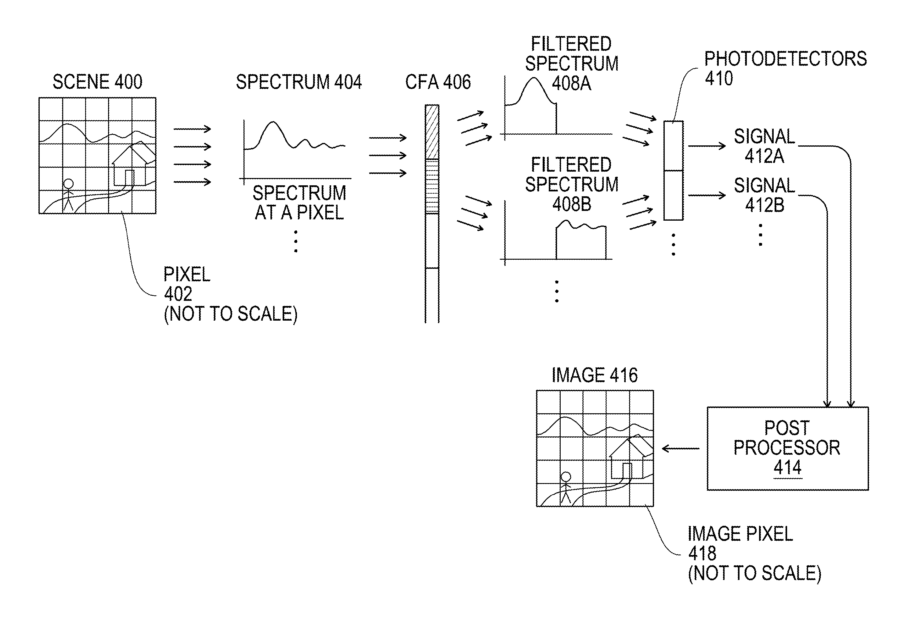
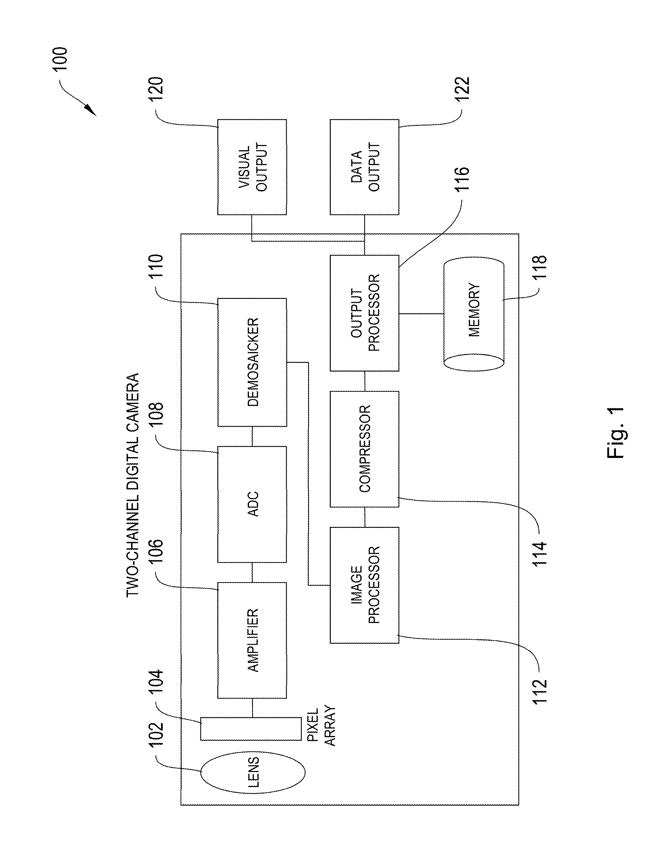
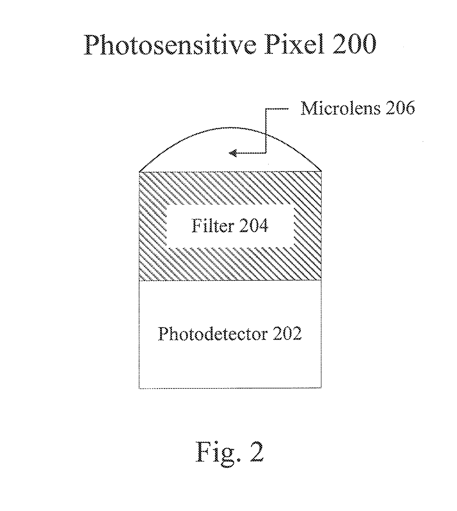
[0046]The systems and methods described herein relate to generating color images using an array of photosensitive pixels. FIG. 1 provides an overview of an exemplary system used to generate such images using two light channels. FIG. 2 depicts a photosensitive pixel used within such a system, while FIG. 3 depicts an array of such pixels. FIG. 4 provides an overview of the image generation process, while FIG. 5 provides an exemplary method for generating a color image. FIG. 6 is a graph illustrating how colors may be distinguished in a two-channel imaging system. FIG. 7 presents an exempla...


PUM


Abstract

Full-color images of low-light scenes are generated by the systems and methods described herein using only two light channels. An array of photosensitive pixels includes two sets of pixels, the first sensitive only to light associated with a first light channel, the second only to light associated with a second light channel. Thus the first set of pixels generate a first set of electrical signals in response to incident light within the first light channel, and the second set of pixels generate a second set of electrical signals in response to incident light within the second light channel. An image processor receives the first and second sets of electrical signals and generates a full-color image of the scene by processing only signals generated by the first and second sets of pixels.

Description

CROSS-REFERENCE TO RELATED APPLICATIONS[0001]This application claims the benefit of U.S. Provisional Application 61 / 576,769 filed Dec. 16, 2011, the teachings of all of which are incorporated herein by reference. This Application claims the benefit of U.S. Provisional Application 61 / 609,762 filed on Mar. 12, 2012, the teachings of all of which are incorporated herein by reference.BACKGROUND[0002]Many fields demand low-light imaging and video. Security cameras must often record minimally illuminated scenes; most marine environments receive little sunlight; the human body does not admit much of the light required for medical endoscopy.[0003]A number of modern image sensor technologies have been developed to satisfy these demands. These modern low-light image sensors are, at their base, a digital camera. A digital camera replaces photosensitive film with an array of photoelectric sensors. The camera lens focuses an image onto the sensor array; each sensor produces an electrical signal ...

Claims


Application Information

Patent Timeline
IPC IPC(8): H01L27/146
CPCH01L27/14645G06T7/90H04N23/555H04N25/585H04N25/11H04N23/843H04N23/88G06F18/22H04N23/10G02B5/208H04N5/33H04N9/77
Inventor JONES, PETER W.J.CARGILL, ELLENPURCELL, DENNIS W.
Owner CHROMATRA
Why Eureka
Try Eureka