
Information processing system, image forming apparatus, and controlling method

Inactive Publication Date: 2013-12-12
CANON KK
View PDF2 Cites 4 Cited by
  • Summary
  • Abstract
  • Description
  • Claims
  • Application Information

AI Technical Summary

Benefits of technology

The technical effect of this patent is to provide a mechanism that prevents multiple users from using the same image forming apparatus at the same time, ensuring the security of each user, even if they use the apparatus through a mobile device.

Problems solved by technology

On the other hand, it is difficult for other users to know who uses the image forming apparatus.
In addition, there is a problem that multi log-in can also occur.
In Japanese Patent Application Laid-Open No. 2007-79639, there is also a problem that it is necessary for a user to perform such a complicated operation as to input a pin number on the display unit of the image forming apparatus in order to identify the user, which is troublesome for the user.

Method used


Image

  • Information processing system, image forming apparatus, and controlling method
  • Information processing system, image forming apparatus, and controlling method
  • Information processing system, image forming apparatus, and controlling method

Examples


exemplary embodiment 1

[0040]One exemplary embodiment of an image forming apparatus according to the present invention will be described below. In the present exemplary embodiment, an SFP printer, in other words, a Single Function Peripheral printer, will be described below as one example of the image forming apparatus. Incidentally, the image forming apparatus includes a multifunctional machine (MFP: Multi Function Peripheral) in which functions of apparatuses such as a copying machine, a facsimile and a scanner are incorporated in one housing, and the present invention can also be applied to such image forming apparatus, other than such an SFP.

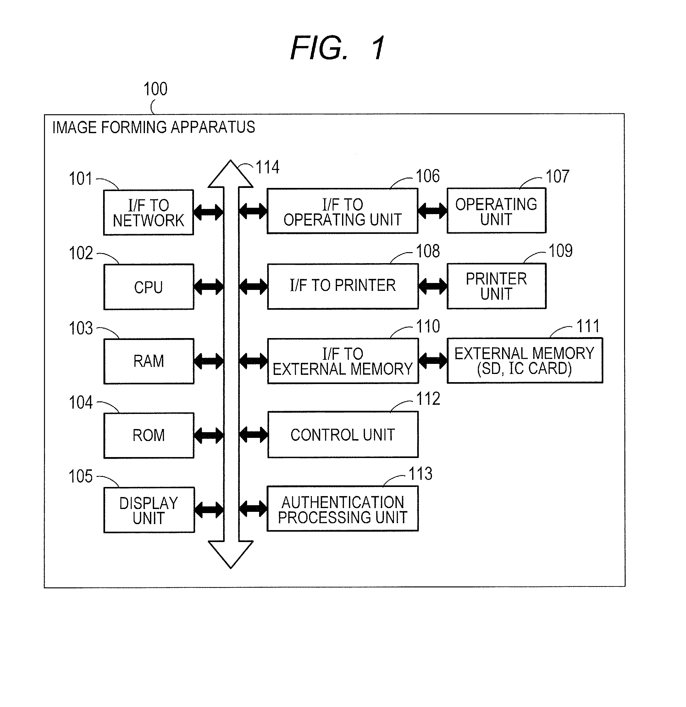
[0041]FIG. 1 is a block diagram illustrating one example of a hardware configuration which illustrates one exemplary embodiment of an image forming apparatus that can be applied to the present invention.

[0042]FIG. 1 shows an image forming apparatus 100 of the present exemplary embodiment.

[0043]In the image forming apparatus 100, an interface 101 to a network (I / F ...

exemplary embodiment 2

[0167]In the above-described Exemplary Embodiment 1, an example has been described in which the mobile terminal 200 reads out a device log-in authentication marker and logs in, and then the marker on the display unit 105 in the image forming apparatus 100 is changed to the application displaying marker.

[0168]However, information on the application, which a user desires to display on a display unit 201 of the mobile terminal 200, is not limited to the information on one application. Accordingly, in Exemplary Embodiment 2, an application displaying list can be displayed so that the applications to be displayed on the mobile terminal 200 can be selected.

[0169]In Exemplary Embodiment 2, the processing will be described which enables a tallying application and a secure print application that are provided in the image forming apparatus 100 to be displayed in the application displaying list, and enables the application to be selected.

[0170]The secure print application has a function of pro...


PUM


Abstract

A control unit 112 of an image forming apparatus generates a first image pattern in which a user information authenticated by an authentication processing unit 113 and an application information concerned with a predetermined application that can be used in the image forming apparatus by the user authenticated are embedded, and displays the first image pattern on a display unit 105. A control unit 208 of a mobile terminal analyzes the first image pattern read out by a camera unit 203 from the display unit 105 of the image forming apparatus to derive the user information and the application information. Furthermore, the control unit 208 of the mobile terminal displays, on a display unit 201 of the mobile terminal, an operation image frame for use a predetermined application corresponding to the derived application information during a period of reading out of the first image pattern by the camera unit 203.

Description

BACKGROUND OF THE INVENTION[0001]1. Field of the Invention[0002]The present invention relates to a technology of displaying information concerning an application installed in an image forming apparatus, and particularly, relates to a technology of controlling a mobile terminal and the image forming apparatus.[0003]2. Description of the Related Art[0004]An image forming apparatus of recent years has improved its image processing function, and as a result, an apparatus provided with various functions has come to be developed. In addition, in the image forming apparatus, many apparatuses employ an LCD (liquid crystal display) panel as an operation display apparatus for operating the display / selection of an application function, or the like.[0005]In addition, mobile terminals of these days such as a mobile telephone and a PDA (Personal Digital Assistant) have come to be multifunctional.[0006]From this background, there are growing demands to transmit information that the mobile terminal...

Claims


Application Information

Patent Timeline
IPC IPC(8): G06K15/00
CPCG06K15/007G06K15/002G06F3/1222G06F3/1236G06F3/1238G06F3/1292G06F21/35G06F21/608H04N1/00334H04N1/00514H04N1/4426H04N1/4433H04N2201/0075H04N1/00
Inventor MURATA, TOMOMI
Owner CANON KK
Learn More