Wireless Branch Circuit Energy Monitoring System

a branch circuit and energy monitoring technology, applied in the field of circuit breakers, can solve the problems of only being able to determine the circuit breaker, so as to reduce the amount of additional materials and labor

Active Publication Date: 2013-12-12
SCHNEIDER ELECTRIC USA INC
View PDF3 Cites 86 Cited by
  • Summary
  • Abstract
  • Description
  • Claims
  • Application Information

AI Technical Summary

Benefits of technology

[0008]Accordingly, the wireless circuit breaker can be implemented using the same package dimensions as existing circuit breakers, allowing the wireless circuit breaker to be a drop-in replacement in an existing panel. In particular, the wireless functionality and power supply can be implemented within the existing package size of a residential MCB,

Problems solved by technology

Many existing circuit breaker panel installations provide only limited information to electricians and consumers about the nature of the fault conditions observed by the circuit breakers.
For example, a residential consumer may only be able to determine that a circuit breaker has tripped, without knowing why.
Ground faults may occur when the electric current is not balanced between an energized line conductor and a neutral conductor, for example when the current is being grounded through a person accidentally touching the circuit.
Arc faults occur with dangerous arcing due to defective or damaged wiring, switches, etc.
However, this data is typically only used by the circuit breaker in making a decision to trip.
However, it is difficult and expensive to retrofit an existing electrical system with circuitry capable of monitoring and aggregating the data from a plurality of circuit breakers.
The additional labor necessary to install the additional circuitry, which would typically be performed by an electrician or engineer, can be involved and expensive.
Ho

Method used


Image

  • Wireless Branch Circuit Energy Monitoring System
  • Wireless Branch Circuit Energy Monitoring System
  • Wireless Branch Circuit Energy Monitoring System

Examples


Embodiment Construction

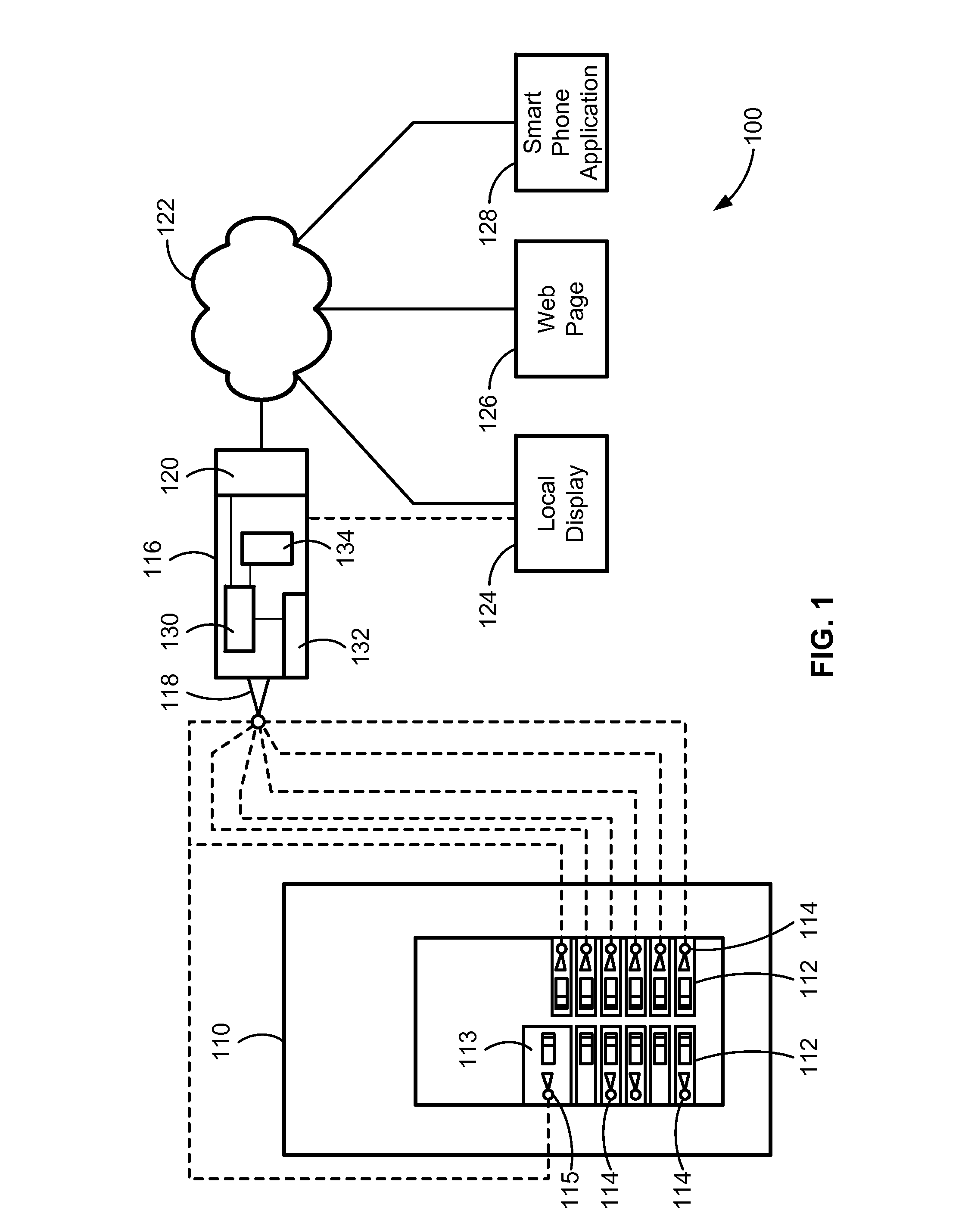
[0017]FIG. 1 shows a block diagram of a circuit breaker monitoring system 100. The circuit breaker monitoring system 100 includes a circuit breaker panel 110 with a plurality of circuit breakers 112. Each circuit breaker 112 includes a radio transmitter / receiver (“transceiver”) 114 for transmitting and receiving wireless data. The panel 110 may be an existing panel in which one or more existing circuit breakers has been replaced with the wireless circuit breakers 112.

[0018]The circuit breaker monitoring system 100 also includes a main energy monitoring module (“main module”) 116 remote from the circuit breaker panel 110. The main module 116 includes a radio transceiver 118 for receiving data transmitted by the radio transceivers 114 of the circuit breakers 112. It also includes a CPU (e.g., a microprocessor, controller, etc.) 130 coupled to the transceiver 118 for processing information received from the circuit breakers 112. The main module 116 may integrated with the panel 110 or ...


PUM


Abstract

A circuit breaker (such as a miniature circuit breaker) that wirelessly communicates state and fault information to a main energy monitoring module. The wireless circuit breaker includes a transceiver and a power supply that harvests energy inductively from the line current conductor without the need for a connection to a neutral conductor. The wireless circuit breaker can be implemented in the same package as existing circuit breakers, eliminating the need to replace the panel when upgrading to a system that employs a main energy monitoring module. The wireless circuit breaker can also include an energy storage device for supplying power to the circuit breaker after it has tripped, allowing the circuit breaker to transmit information after a trip. The main energy monitoring module includes a processor and a gateway for evaluating and transmitting information received from the circuit breaker to other applications, such as webpages and smartphones.

Description

FIELD OF THE INVENTION[0001]The invention relates to circuit breakers, and more particularly to wireless circuit breakers.BACKGROUND OF THE INVENTION[0002]Circuit breakers provide protection in electrical systems by monitoring characteristics of the electrical power supplied to loads over electrical conductors and interrupting or breaking the circuits (tripping) when fault conditions (e.g., arc faults, ground faults, and unsafe “over current” levels) are detected. Circuit breakers are typically installed in circuit breaker panels, or load centers, often in utility rooms for commercial applications and basements for residential applications.[0003]Many existing circuit breaker panel installations provide only limited information to electricians and consumers about the nature of the fault conditions observed by the circuit breakers. For example, a residential consumer may only be able to determine that a circuit breaker has tripped, without knowing why. More sophisticated circuit break...

Claims


Application Information

Patent Timeline
IPC IPC(8): H02H3/08
CPCH02H1/0084H02H1/06H01H9/168H01H83/226H01H71/04H02H3/04H02H3/16H01H71/125
Inventor ERGER, ROBERTBROGHAMMER, WILLIAMLARSON, BRETTREID, PAUL A.
Owner SCHNEIDER ELECTRIC USA INC
Why Eureka
Try Eureka