Method and apparatus for zero-sequence damping and voltage balancing

a zero-sequence damping and voltage balancing technology, applied in the field of multi-level inverters, can solve problems such as severe adverse effects, capacitor voltage imbalance, and capacitor voltage balancing issu

Active Publication Date: 2013-12-12
ABB (SCHWEIZ) AG
View PDF3 Cites 61 Cited by
  • Summary
  • Abstract
  • Description
  • Claims
  • Application Information

AI Technical Summary

Benefits of technology

[0030]An additional resonance can also be induced by a DC-link capacitor voltage imbalance and zero-sequence components LCL-filter of the inverter-side current and voltage. The disclosed method can attenuate the zero-sequence resonance by actively inserting an appropriate damping. Compared with passive damping methods, where resistors have to be inserted in the LCL-filter, the use of an active damping method, allows reduction in losses.

Problems solved by technology

Balancing of capacitor voltages is an issue which can naturally arise in multilevel topologies, or whenever the DC-link voltage is split in a topology for a special purpose, for instance, to allow connection to a neutral grid point.
Another issue in three-phase inverters involves the generation of common-mode voltage (CMV).
CMV is an issue which can be associated with the inverter topology and the modulation algorithm used.
CMV can, for example, be induced by an inverter itself, and can then be propagated to the equipment connected to the inverter, causing severe adverse effects.
The zero-sequence voltage fluctuation can, depending on the application, cause indirect grid current distortion, additional losses and safety issues, among other things as described in document [6].
For instance, CMV in electric drives can create bearing currents which can cause physical damage to electrical machines.
CMV can also cause considerable leakage current to flow through the parasitic capacitances of photovoltaic (PV) panels supplying an inverter.
However, this modification reduces utilization of the DC voltage, e.g., it limits the modulation index.
However, when switching states are restricted, it is no longer possible to guarantee the balance of capacitor voltages.
The added fourth leg can, however, increase the complexity and decrease the cost-effectiveness of the inverter.
On the other hand, resistors in the filter introduce additional losses to the system, thus, reducing the efficiency of the system.

Method used


Image

  • Method and apparatus for zero-sequence damping and voltage balancing
  • Method and apparatus for zero-sequence damping and voltage balancing
  • Method and apparatus for zero-sequence damping and voltage balancing

Examples


Embodiment Construction

[0026]Exemplary embodiments of the present disclosure provide a method and an apparatus so as to alleviate the above disadvantages.

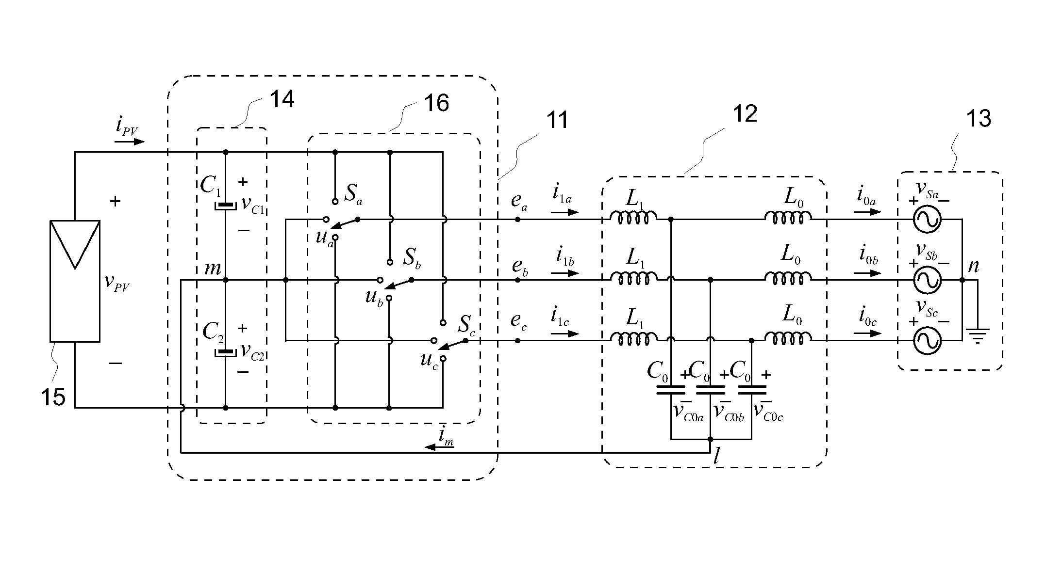
[0027]This result can be achieved through a multi-phase inverter connected to the grid through an LCL-filter. The inverter topology includes an artificial mains neutral star point connection, which is referred in this disclosure as a virtual-ground (VG) connection. The VG represents a good option for the minimization of the CMV. In order to form the VG, a star point formed by the capacitors of the LCL-filter is connected to a mid-point of the DC-link.

[0028]The use of a virtual-ground allows also maximum utilization of the DC-link voltage. The DC-link voltage can be lowered by using a third-harmonic reference injection method. Thus, semiconductor devices in the inverter bridge of the inverter can be exposed to lower voltages, which, in turn, can reduce losses.

[0029]Since the capacitors in the DC-link are split, and the DC-link has a VG connection, a volta...


PUM


Abstract

An exemplary method and an apparatus implementing the method for an arrangement having a three-phase, multi-level inverter, an output LCL-filter connecting the inverter to a grid, and a virtual-ground connection between the LCL-filter and the neutral point of the DC-link. The method includes determining a zero-sequence component of an LCL-filter inverter-side current, calculating a zero-sequence damping and balancing voltage term based on the LCL-filter inverter-side current zero-sequence component and voltages over the two halves of the DC-link, and adding the zero-sequence damping and voltage balancing term to the output voltage reference.

Description

RELATED APPLICATION(S)[0001]This application claims priority under 35 U.S.C. §119 to European Patent Application No. 12171143.6 filed in Europe on Jun. 7, 2012, the content of which is hereby incorporated by reference in its entirety.FIELD[0002]The present disclosure relates to multi-level inverters, and particularly to minimizing common-mode voltage and imbalances in DC-link voltages.BACKGROUND INFORMATION[0003]Balancing of capacitor voltages is an issue which can naturally arise in multilevel topologies, or whenever the DC-link voltage is split in a topology for a special purpose, for instance, to allow connection to a neutral grid point. Solutions for this issue have been largely reported in the literature [1]-[2].[0004]In document [1], the authors propose use of an energy function which is minimized in real time by evaluating redundant control vectors of a multi-level converter. A similar idea is followed in document [2] where the authors explore two strategies also based on the...

Claims


Application Information

Patent Timeline
Patent Type & Authority Applications(United States)
IPC IPC(8): H02M7/42
CPCH02M1/126H02J3/383Y02E10/563H02M2001/123H02M7/42H02M7/487H02J2300/24H02J3/381Y02E10/56H02M1/0003H02M1/123H02M7/4833
Inventor ESCOBAR, GERARDOPETTERSSON, SAMIHO, NGAI-MAN
Owner ABB (SCHWEIZ) AG
Why Eureka
Try Eureka