

Laboratory Fume Hood System Having Recessed Heat Exchanger System
a technology of heat exchanger and fume hood, which is applied in ventilation systems, heating types, stoves or ranges, etc., can solve the problems of reducing the risk of leakage or flooding within the interior work area of the fume hood and/or the surrounding laboratory, and achieve the effect of reducing the risk of leakage or flooding
Active Publication Date: 2013-12-12
UNIVERSITY OF KANSAS
View PDF6 Cites 3 Cited by
- Summary
- Abstract
- Description
- Claims
- Application Information
AI Technical Summary
Benefits of technology
The present invention is a laboratory fume hood system that uses a heat exchanger to cool down devices in the fume hood. The heat exchanger is located outside of the fume hood and in thermal communication with the device(s) through a cooling fluid. This setup prevents any leaks or flooding in the laboratory and conserves space. The technical effect is to provide a safe and efficient way to cool down laboratory devices without using up valuable space in the laboratory interior.
Problems solved by technology
This significantly decreases the risk of leaks or flooding within the fume hood interior work area and / or the surrounding laboratory.
Method used
View moreImage
Smart ImageViewing Examples

Examples
example
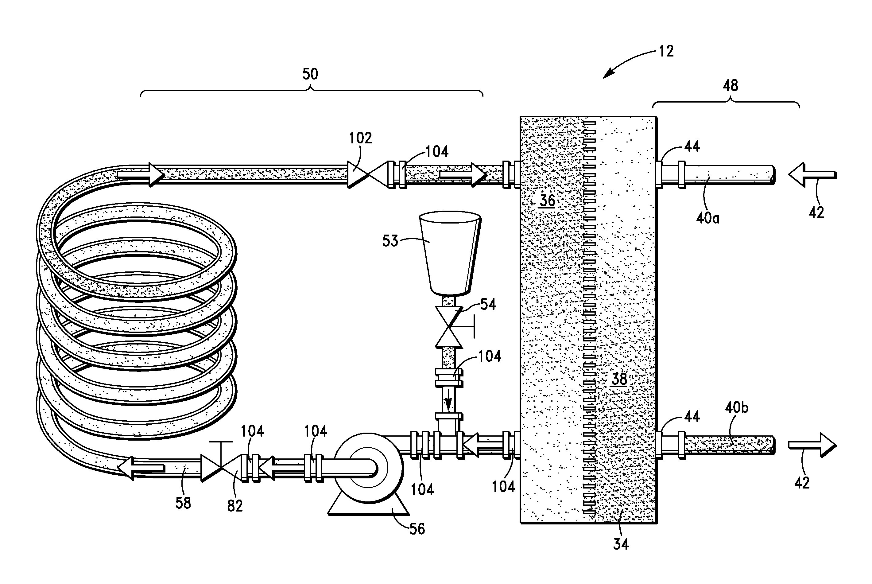
[0043]A laboratory fume hood system was constructed. The heat exchanger was a brazed plated heat exchanger (AIC L-Line Series, LB31-10, 90,000 BTU / hour, 6.2 GPM, 5.1 psi). The primary loop comprised a chilled water supply maintained at about 48° F. and about 15 psi and circulated through a stainless steel hose (90 psi). The secondary fluid loop comprised a March AC-3CP-MD variable volume pump (10 GPM, maximum head 50 psi). Various 90 degree hose fittings and union tees (G. A. Murdock, Q0820816, V0820826) were used to connect the polyethylene tubing.
Login to View More PUM
| Property | Measurement | Unit |
|---|---|---|
| temperature | aaaaa | aaaaa |
| exit temperature | aaaaa | aaaaa |
| temperature | aaaaa | aaaaa |
Abstract
A laboratory fume hood system for cooling at least one laboratory device located in an interior work area comprises a heat exchanger system having a heat exchanger in thermal communication with a primary fluid loop containing chilled fluid and a secondary fluid loop containing a cooling fluid which is in thermal communication the laboratory device. The primary fluid loop is located behind the fume hood wall and not in the interior work area.
Description
CROSS-REFERENCE TO RELATED APPLICATIONS[0001]This application is based on and claims priority to U.S. Provisional Application Ser. No. 61 / 682,951, filed on Aug. 14, 2012, and is a continuation-in-part of U.S. Ser. No. 12 / 393,362, filed on Feb. 26, 2009, each of which is incorporated herein by reference in its entirety.STATEMENT REGARDING FEDERALLY SPONSORED RESEARCH OR DEVELOPMENT[0002]Not applicable.BACKGROUND OF THE INVENTION[0003]Laboratory environments present many challenges for instrument design and the conducting of experiments and procedures. In particular, chemistry laboratories often contain fume hoods with equipment that require the circulation of cooling fluid therein. Such equipment may include, but is not limited to, rotary evaporators, lasers, reflux condenser columns, distillation columns, etc. These types of equipment are commonly used in universities and research and development entities.[0004]Various techniques are known in the art for providing the necessary cool...
Claims
Login to View More Application Information
Patent Timeline
 Patent Type & AuthorityApplications(United States)
IPC IPC(8): B08B15/02F28D15/00B23P19/00B01L7/00
CPCB01L1/50B01L2300/185B08B15/023Y10T29/49826F28D15/00B23P19/00B01L7/00F28D2021/0019
InventorWILSON, GEORGE S.JEFFRESS, WILLIAM SCOTTSCHOENEN, FRANK J.
OwnerUNIVERSITY OF KANSAS