Superresolution imaging of scatterers in pulse-echo imaging

Active Publication Date: 2013-12-12
UNIVERSITY OF ROCHESTER
View PDF5 Cites 3 Cited by
  • Summary
  • Abstract
  • Description
  • Claims
  • Application Information

AI Technical Summary

Benefits of technology

[0030]To achieve the above and other objects, the present invention is directed to an approach to an inverse filter solution with stabilized ultrasound pulses. Stabilized pulses, in this context, are realizable continuous functions in the axial and transverse directions that when sampled have their Z-transform zeroes lying within the unit circle. This corresponds to inverse filters that are stable because their poles lie within the unit circle, such that they are limited in time with bounded output. By applying an exact, stable inverse filter, the final result is a very high resolution, subwavelength solution to the distribution of scatterers that were previously below the resolution of the ultrasound pulse and the imaging system. The integration of random scatterers over the pulse length and width is essentia

Problems solved by technology

The problems with a visual interpretation of speckle images are profound, since the patterns of nulls and peaks may or may not correspond to actual nulls or peaks of the scatterers, but rather to their summation over the positive and negative portions of the propagating pulse.
Furthermore, the lesion detection proble

Method used


Image

  • Superresolution imaging of scatterers in pulse-echo imaging
  • Superresolution imaging of scatterers in pulse-echo imaging
  • Superresolution imaging of scatterers in pulse-echo imaging

Examples


Example

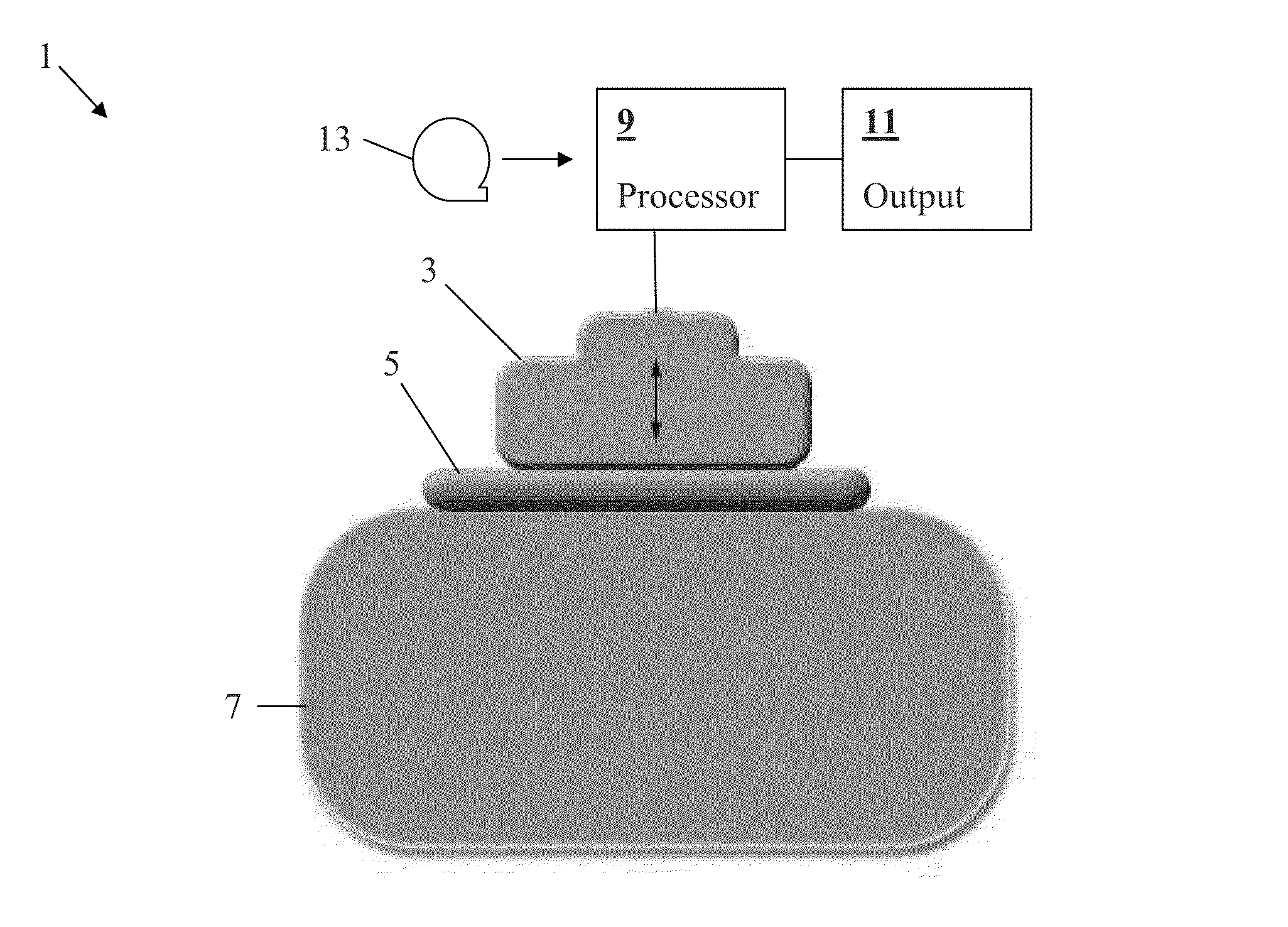
[0061]A preferred embodiment will now be set forth in detail with reference to the drawings, in which like reference numerals refer to like elements or steps throughout.

[0062]We begin with a discrete version of Equation (1) with the inclusion of noise. Without loss of generality, the 2D version is given as:

e[n]=p[n]s[m]**R[n,m]+g[n,m]  (2)

[0063]where g[n,m] is additive noise.

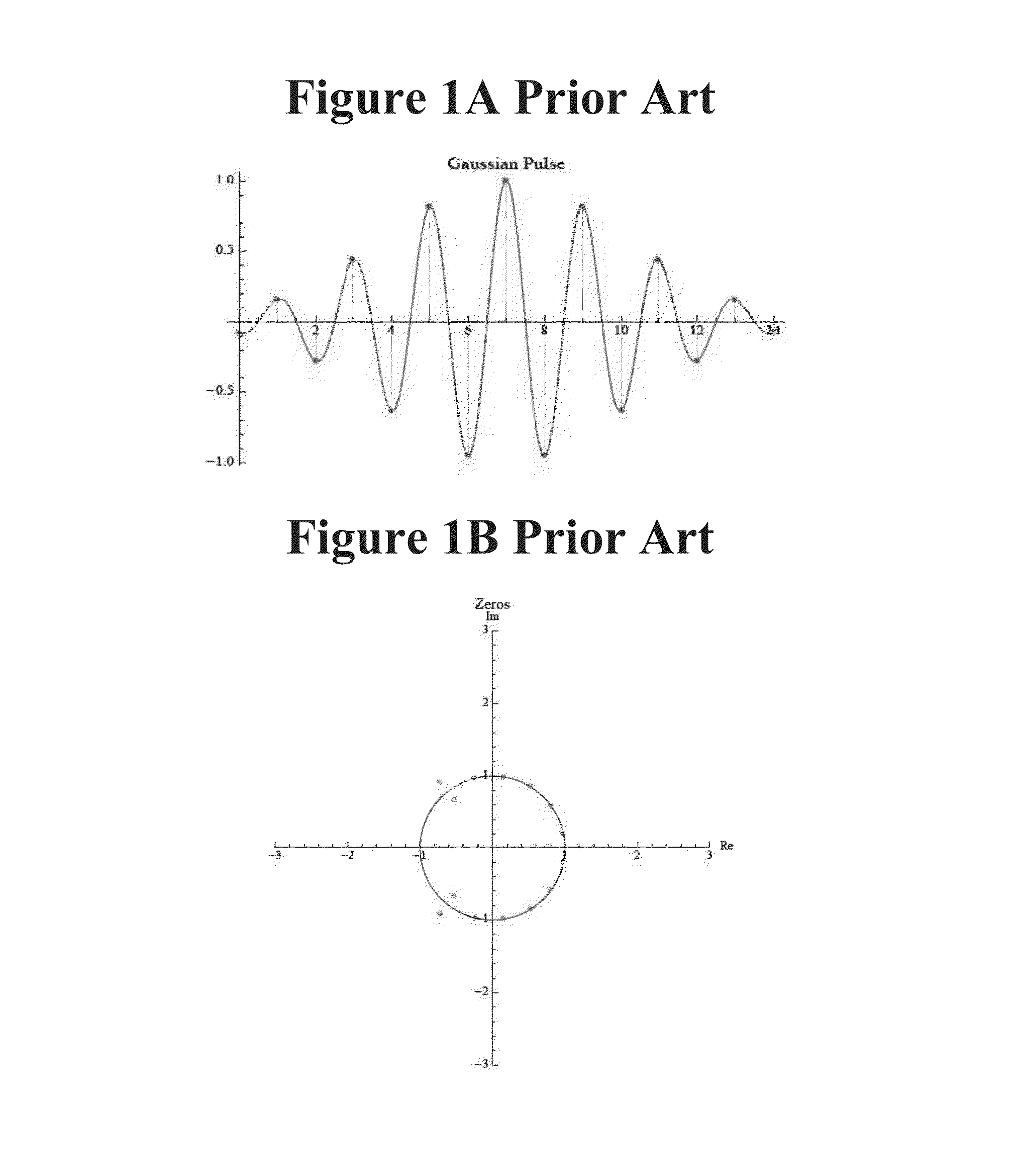
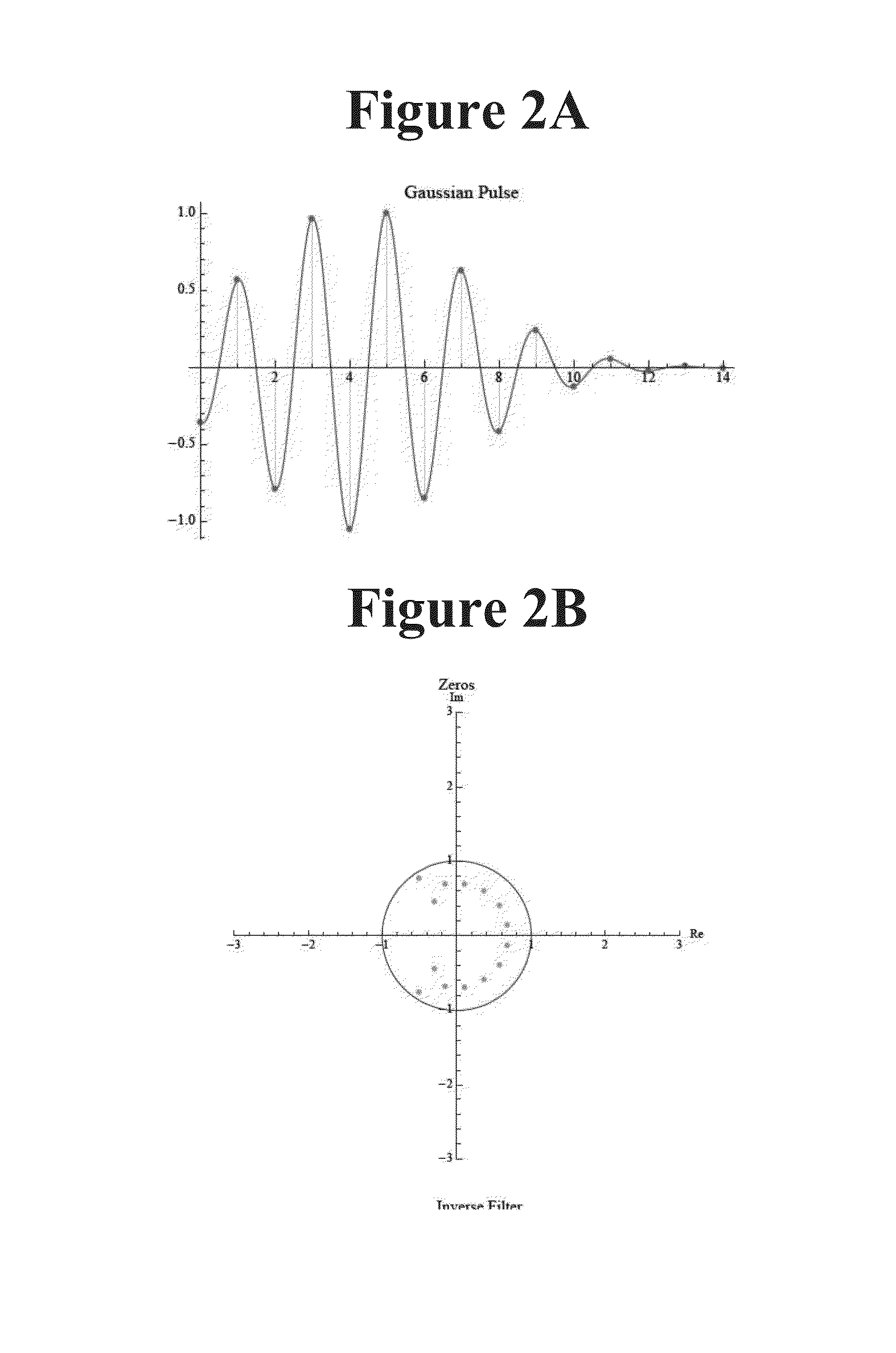
[0064]The objective is to reconstruct the scatterers or reflectors R[n,m]. For this we turn to the Z-transform of p[n]. The one-sided Z-transform of p[n] is given by (Oppenheim and Schafer 1975):

P(z)=∑0∞p[n]z-n(3)

[0065]For a pulse of length N, the Z-transform is a polynomial of order N−1, which can be factored into roots, giving zeros of the Z-transform. The inverse filter, given by the transform 1 / P(z), will convolve with p[n] to produce an impulse. However, it is clear that the reciprocal nature of P(z) and its inverse filter transform implies that the zeroes of the pulse transform P(z) become the poles of the...


PUM


Abstract

In ultrasound B-scan imaging or other pulse-echo imaging, an inverse filter solution eliminates both the speckle phenomenon and the poor resolution dependency on the pulse length and width to produce SURUS (super-resolution ultrasound) images. The pulse shapes have stable inverses, derived by use of the standard Z-transform and related properties.

Description

FIELD OF THE INVENTION[0001]The present invention is directed to pulse-echo imaging, such as ultrasound imaging, and more particularly to such imaging that uses a transform to achieve superresolution.DESCRIPTION OF RELATED ART[0002]At the heart of analytical models of pulse-echo imaging is an integration on the product of the propagating pulse and the reflectors or scatterers, over the location of the pulse at some point in time (Macovski 1983; Szabo 2004; Prince and Links 2006). Under a number of approximations and simplifications about attenuation and diffraction, the integration can be reduced to a convolution model (Macovski 1983) such that the received echo e(t) is approximated by:e(t)=A{p(t)s(x,y)⋆⋆⋆R(x,y,ct2)}(1)[0003]where A is an amplitude constant, p(t) is the propagating pulse in the axial direction, s(x,y) is the beam width in the transverse and elevational axes (and thus the beam pattern is assumed to be a separable function), and R(x,y,z) is the 3D pattern of reflector...

Claims


Application Information

Patent Timeline
IPC IPC(8): A61B8/14
CPCG01S15/8977A61B8/5207A61B8/0883G01S7/52047
Inventor PARKER, KEVIN J.
Owner UNIVERSITY OF ROCHESTER
Why Eureka
Try Eureka