Laminar flow droplet generator device and methods of use

Active Publication Date: 2013-12-19
EYENOVIA
View PDF4 Cites 19 Cited by
  • Summary
  • Abstract
  • Description
  • Claims
  • Application Information

AI Technical Summary

Benefits of technology

[0005]According to the disclosure, a piezoelectric ejector device is provided which is designed to minimize the intake of air into the device upon actuation, as explained in further detail herein. The ejector mechanism may include a generator plate and a piezoelectric actuator operable to directly or indirectly oscillate the generator plate, at a frequency to generate a directed stream of droplets of fluid. The generator plate includes a fluid facing sur

Problems solved by technology

However, a major challenge in providing such a device is to provide consistent and accurate delivery of suitable doses.
In addition, a

Method used


Image

  • Laminar flow droplet generator device and methods of use
  • Laminar flow droplet generator device and methods of use
  • Laminar flow droplet generator device and methods of use

Examples


Embodiment Construction

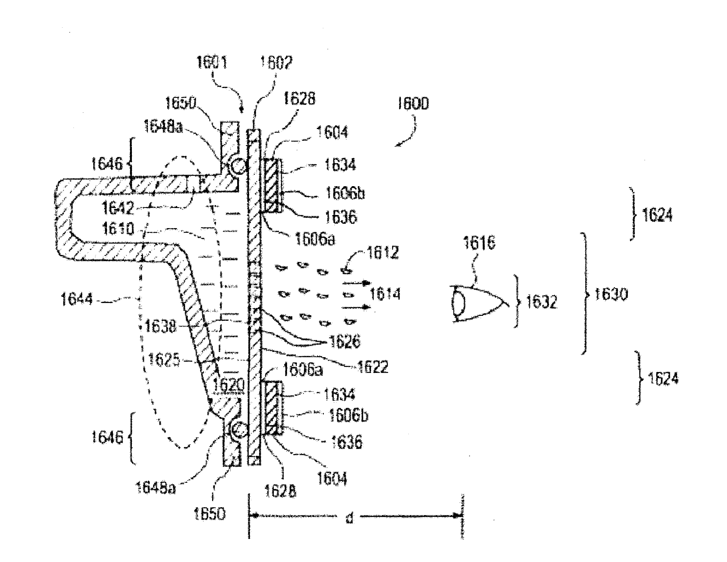
[0024]The present disclosure generally relates to piezoelectric ejector devices useful, e.g., in the delivery of fluids, such as ophthalmic fluids to the eye. The ejector device may include an ejector assembly including an ejector mechanism and a fluid supply. In certain aspects, the ejector mechanism may comprise a piezoelectric actuator and a droplet generator plate, which are operable to generate a directed stream of droplets of fluid when the actuator is actuated to directly or indirectly oscillate the generator plate. Fluid includes without limitation, suspensions or emulsions which have viscosities in a range capable of droplet formation using an ejector mechanism.

[0025]Piezoelectric droplet generation and flow in micro-channels depends on a complex interaction between liquid flow through micro-orifices, fluid-surface interactions, exit orifice diameter, entrant cavity geometry, capillary tube length, ejector material mechanical properties, amplitude and phase of the mechanica...


PUM


Abstract

A piezoelectric ejector device is provided which is designed to minimize the intake of air into the device upon actuation by providing for laminar flow of the fluid. In an ejector mechanism that includes a generator plate and a piezoelectric actuator operable to directly or indirectly oscillate the generator plate, at a frequency to generate a directed stream of droplets of fluid, the generator plate includes a fluid facing surface, a droplet ejection surface, and a plurality of holes formed through its thickness between the surfaces. The plurality of holes are configured so as to minimize airflow through the plurality of openings from the droplet ejection surface to the fluid facing surface during generation of the directed stream of droplets by configuring the shape of the holes to minimize turbulence.

Description

RELATED APPLICATIONS[0001]The present application claims the benefit of the filing date of U.S. Patent Application Nos. 61 / 646,721, filed May 14, 2012, entitled “Ejector Mechanism, Ejector Device and Methods of Use” and 61 / 722,600 filed Nov. 5, 2012, entitled “Laminar Flow Droplet Generator Device and Methods of Use”, the contents of which are herein incorporated by reference in their entireties.BACKGROUND OF THE INVENTION[0002]Using spray devices to administer products in the form of mists or sprays is an area with large potential for safe, easy-to-use products. An important area where spray devices are needed is in delivery of eye medications. However, a major challenge in providing such a device is to provide consistent and accurate delivery of suitable doses. In addition, a multi-dose spray device may become exposed to possible contamination as a result of interaction with a non-sterile outside environment.[0003]Accordingly, there is a need for a delivery device that delivers sa...

Claims


Application Information

Patent Timeline
IPC IPC(8): B05B17/00
CPCB05B17/0646B06B1/0651B05B17/0669B05B17/0661A61F9/0008B05B15/50B05B1/28B05B17/06B05B7/0012B05B17/0607B05B1/14B05B1/02F02M61/1853A61M15/0065A61M15/0085
Inventor WILKERSON, JONATHAN RYANLYNCH, IYAMGERMINARIO, LOUIS THOMASHUNTER, CHARLES ERIC
Owner EYENOVIA
Why Eureka
Try Eureka