
Dynamic Braking on a Wind Turbine During a Fault

a technology of dynamic braking and wind turbine, which is applied in the direction of dynamo-electric converter control, electric generator control, machines/engines, etc., can solve the problems of increasing the cost of the machine, both of initial manufacture, maintenance or replacement,

Inactive Publication Date: 2013-12-19
CLIPPER WINDPOWER INC
View PDF0 Cites 32 Cited by
  • Summary
  • Abstract
  • Description
  • Claims
  • Application Information

AI Technical Summary

Benefits of technology

The patent describes a braking system for a wind turbine that includes a DC chopper and a super capacitor connected to a DC bus through a switch. The system also includes a control system for controlling the operation of the DC chopper. The technical effect of the patent is to provide a reliable and efficient braking system for wind turbines that can handle fault conditions, including overvoltage or short-circuiting, to ensure safe and reliable operation of the wind turbine.

Problems solved by technology

While effective, this also increases the cost of the machine, both of initial manufacture, and of maintenance or when replacement is needed.
Furthermore, grid disturbances that result in unloading of wind turbine generator(s) expose the wind turbines' converters / inverters to full open circuit voltage of the generator(s).

Method used


Image

  • Dynamic Braking on a Wind Turbine During a Fault
  • Dynamic Braking on a Wind Turbine During a Fault
  • Dynamic Braking on a Wind Turbine During a Fault

Examples


Embodiment Construction

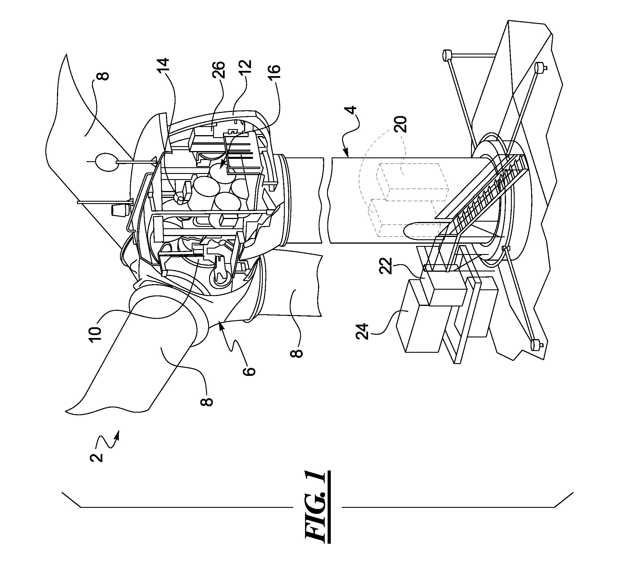
[0024]Referring to FIG. 1, an exemplary wind turbine 2 is shown, in accordance with at least some embodiments of the present disclosure. While all the components of the wind turbine have not been shown and / or described, a typical wind turbine may include a tower section 4 and a rotor 6. The rotor 6 may include a plurality of blades 8 that rotate with wind energy and transfer that energy to a main shaft 10 situated within a nacelle 12. The nacelle 12 may additionally include a low-speed shaft (not visible) driven by the main shaft 10, a gearbox 14 connecting the low speed shaft to a high speed shaft (also not visible) and, one or more generators 16 driven by the high speed shaft to generate electric current and, particularly, alternating current (AC).

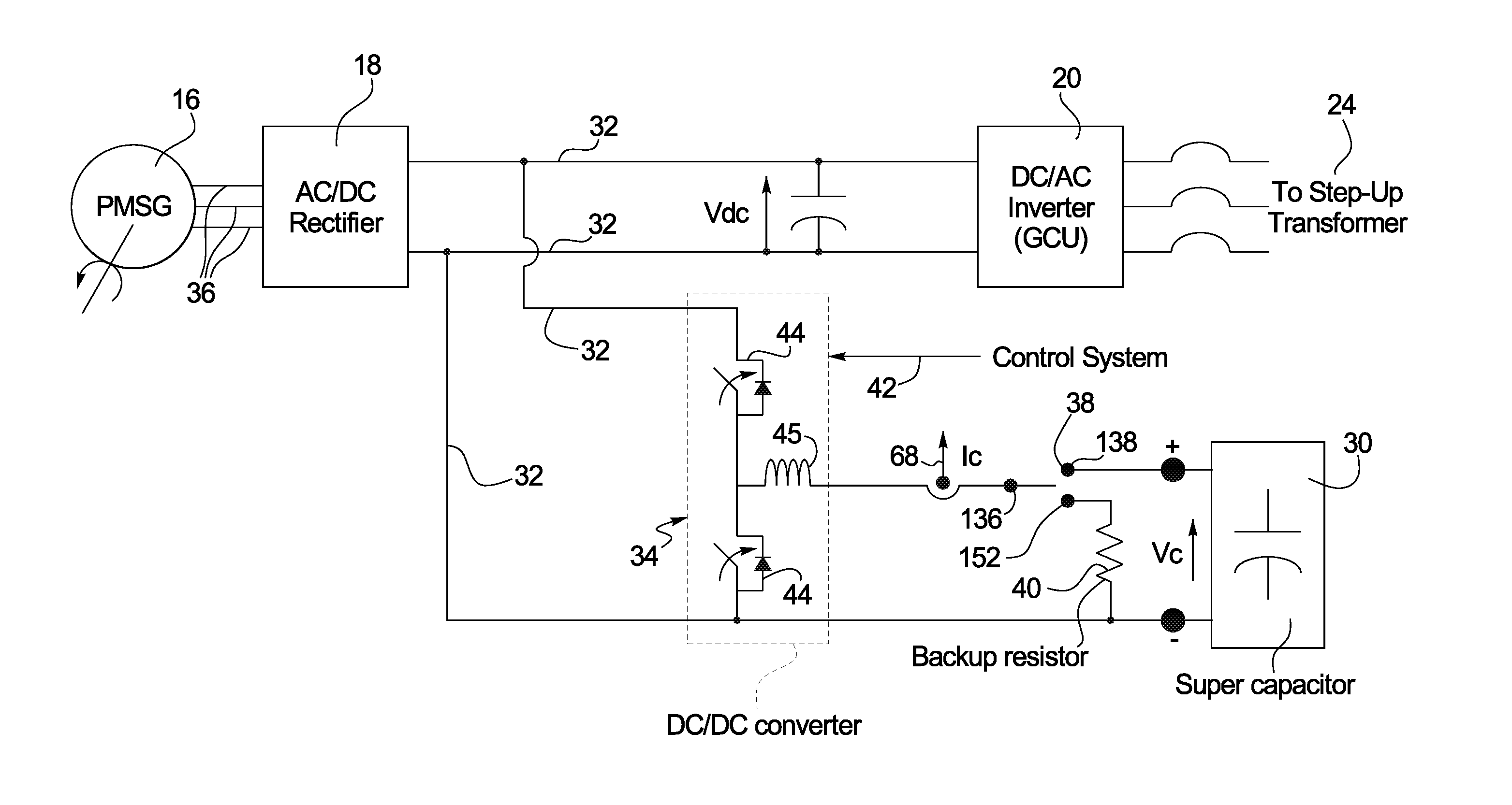
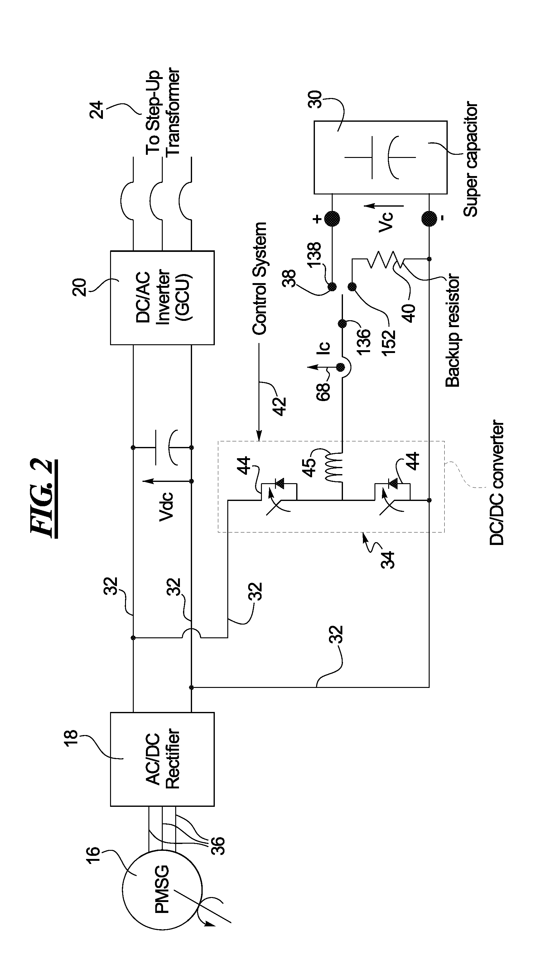
[0025]The AC current from the generators 16 may be provided to one or more rectifiers 18 (See FIG. 2) that may convert the AC current into a direct current (DC) for transmission. The rectifiers 18 may be situated within the nacelle 12 or...


PUM


Abstract

A braking system for a wind turbine is disclosed. The braking system may include a DC chopper connected to a DC bus and a super capacitor capable of being connected to the DC chopper through a switch. The DC chopper may be controlled by a control system to enable one of charging, discharging, idle or system off modes of the super capacitor.

Description

FIELD OF THE DISCLOSURE[0001]The present disclosure generally relates to wind turbines and, more particularly, relates to dynamic braking on wind turbines during fault conditions.BACKGROUND OF THE DISCLOSURE[0002]As wind turbines increase in size and power, larger and larger loads are exerted on the tower and the drive train of the wind turbine during various fault conditions, such as, grid disturbances, wind gusts, and other emergency feather conditions. As a result, the tower and drive train are manufactured heavier and more structurally reinforced. While effective, this also increases the cost of the machine, both of initial manufacture, and of maintenance or when replacement is needed.[0003]Another option is to use dynamic braking during fault conditions to help control the rotor speed of a wind turbine. This may be done in lieu of, or in addition to increasing the weight of the tower and the drive train. One common dynamic braking system uses a resistor on the DC bus, and usual...

Claims


Application Information

Patent Timeline
IPC IPC(8): H02P9/10F03D9/00
CPCF03D7/0264F05B2260/903Y02E10/723H02P9/107H02P3/22Y02E10/72
Inventor MASHAL, HANIFMOTAPON, SOULEMAN NJOYA
Owner CLIPPER WINDPOWER INC
Learn More