Charging cable for electrically-driven vehicle

a charging cable and vehicle technology, applied in the direction of secondary cell servicing/maintenance, electric devices, batteries, etc., can solve the problems of prolonged charging time and problematic charging cable, and achieve the effects of reducing charging current, enhancing durability, and reducing charging tim

Active Publication Date: 2013-12-19
PANASONIC INTELLECTUAL PROPERTY MANAGEMENT CO LTD
View PDF2 Cites 46 Cited by
  • Summary
  • Abstract
  • Description
  • Claims
  • Application Information

AI Technical Summary

Benefits of technology

[0012]In the electrically-driven vehicle, the charging current to the built-in battery is controlled based on the pilot signal sent from the controller. According to the present invention, because the charging current to the electrically-driven vehicle is variably set depending on the temperature of the power plug, the controller or the charging coupler of the charging cable, the charging of the battery can be continued with a reduced charging current when the temperature of, for example, the power plug, the controller or the charging coupler increases. This feature can reduce the charging time and enhance the durability of, for example, relays, as compared with the conventional on / off control.
[0013]Also, because a first temperature detector is provided in the power plug and / or the charging coupler and a second temperature detector is provided in the controller, the controller can easily determine failures such as disconnection of the temperature detector provided in the power plug or the charging coupler by comparing outputs from the two temperature detector with each other, thereby making it possible to enhance the reliability of the equipment.

Problems solved by technology

However, the charging cable as disclosed in Patent Document 1 halts power supply from the power plug to the connector of the electrically-driven vehicle if the temperature sensor detects that the temperature of the power plug or the charging coupler has exceeded the predetermined temperature or the earth leakage detecting portion detects the earth leakage.
Accordingly, if lengthy energization is required as with the electrically-driven vehicle, the charging cable is problematic in that the charging time is prolonged or in durability of, for example, relays due to on / off controls.

Method used


Image

  • Charging cable for electrically-driven vehicle
  • Charging cable for electrically-driven vehicle
  • Charging cable for electrically-driven vehicle

Examples


embodiment 1

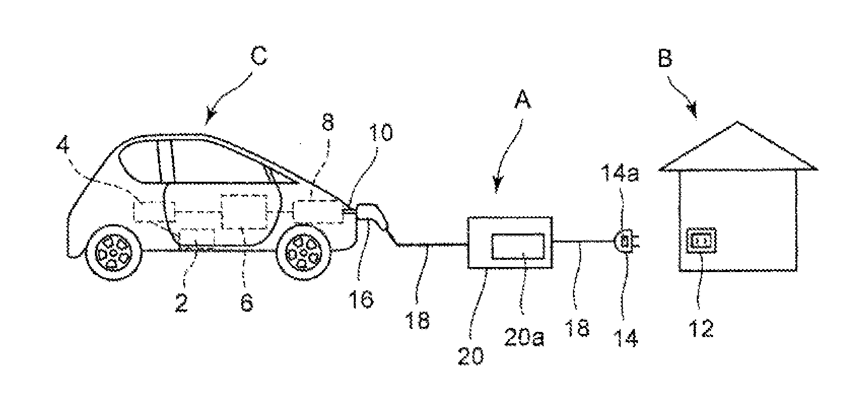
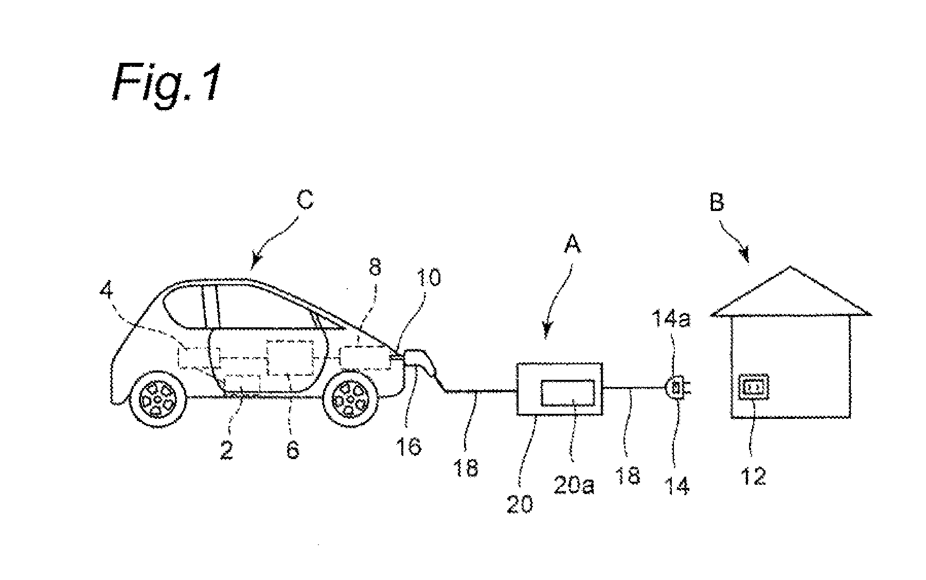
[0034]FIG. 1 depicts a state where a battery of an electrically-driven vehicle C is electrically charged from a commercially available power source of a standard home B using a charging cable A for an electrically-driven vehicle according to the present invention.

[0035]As shown in FIG. 1, the electrically-driven vehicle C is provided with a drive motor 2, an inverter 4, a battery 6 and a charge control device 8, all electrically connected to one another. The electrically-driven vehicle C is connected to the charging cable A for the electrically-driven vehicle (hereinafter referred to simply as the “charging cable”) via a connector 10 connected to the charge control device 8. The charging cable A is used to connect a receptacle outlet 12 provided on, for example, an outer wall of the standard home B to the connector 10 on the side of the electrically-driven vehicle C to charge the battery 6 installed in the electrically-driven vehicle C.

[0036]The receptacle outlet 12 is an outlet or ...

embodiment 2

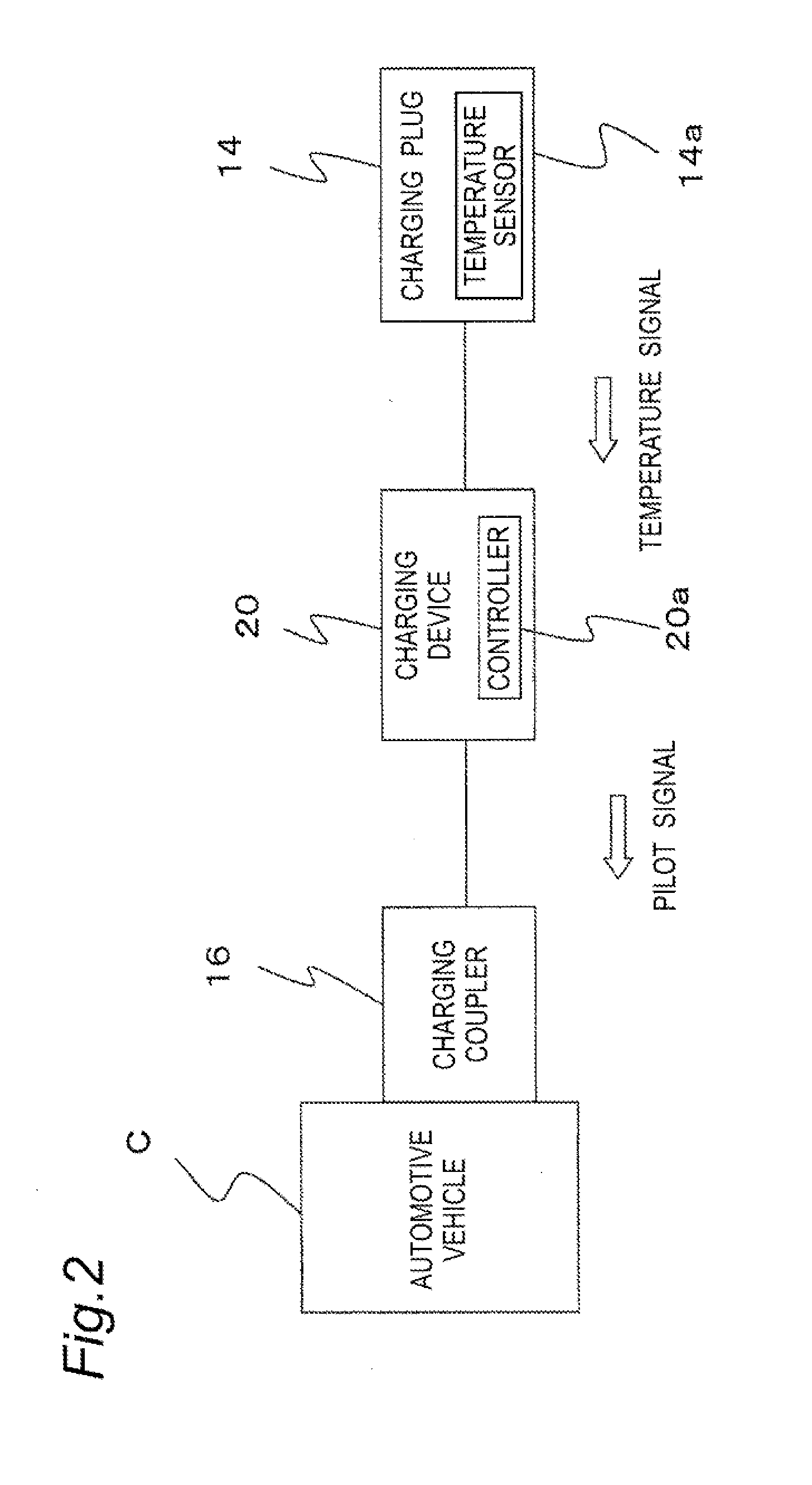
[0064]FIGS. 5 and 6 depict a second embodiment of the present invention. FIG. 5 is a schematic view depicting a state where a battery of an electrically-driven vehicle is electrically charged using a charging cable according to the second embodiment of the present invention and FIG. 6 is a schematic block diagram of the charging cable shown in FIG. 5. In the second embodiment of the present invention, a temperature sensor 16a is provided in the charging coupler 16. The temperature sensor 16a detects the temperature of the charging coupler 16 and outputs a temperature signal indicating the temperature of the charging coupler 16 to the controller 20a of the charging device 20. Upon receipt of the temperature signal, the controller 20a outputs a pilot signal corresponding to the temperature signal to the charge control device 8 of the electrically-driven vehicle C via the charging coupler 16. The charge control device 8 can recognize, based on the pilot signal received, the charging cu...

embodiment 3

[0066]FIG. 7 is a schematic block diagram of a charging cable according to a third embodiment of the present invention, in which a temperature sensor 20b is provided in the controller 20a of the charging device 20. It is assumed that the charging of the electrically-driven vehicle C is conducted under various circumstances and that the controller 20a abnormally generates heat, for example, with the charging device 20 left in the hot sun. It is also assumed that abnormal heat generation may occur due to incomplete connection or arc tracking at, for example, connecting portions between the connecting cable 18 of the controller 20a and terminals. In the third embodiment, the temperature sensor 20a provided in the controller 20 can prevent abnormal heat generation in the controller 20a, thus making it possible to produce similar effects as in the above-described first embodiment.


PUM


Abstract

A charging cable A for use in charging a battery of an electrically-driven vehicle includes a power plug 14 to be detachably connected to a receptacle outlet 12 of a commercially available power source, a charging coupler 16 to be detachably connected to the electrically-driven vehicle C, a temperature sensor 14a for detecting a temperature of an electric circuit between the power plug 14 and the charging coupler 16, and a charging device 20 having a controller 20a for controlling a current value that flows from the power plug 14 to the charging coupler 16. This configuration can minimize the charging time and enhance the durability between the charging cable and the receptacle outlet and between the charging cable and the charging coupler.

Description

TECHNICAL FIELD[0001]The present invention relates to a charging cable for an electrically-driven vehicle for use in charging a battery of an electrically-driven vehicle such as, for example, an electric vehicle or a hybrid vehicle.BACKGROUND ART[0002]In recent years, electrically-driven vehicles are being developed as environmentally-friendly automobiles at a rapid pace. Charging infrastructures for the electrically-driven vehicles are largely classified into a charging facility for home use that utilizes a household power source at the end of a power network and another charging facility for public use that is available to the general public and provided in an urban area, beneath a road surface or the like.[0003]Also, in view of convenience, the charging facility for home use is required for the popularization of the electrically-driven vehicles and, hence, standard homes, offices and the like have started introducing a slow charging facility that utilizes a commercially available...

Claims


Application Information

Patent Timeline
Patent Type & Authority Applications(United States)
IPC IPC(8): B60L11/18
CPCB60L11/185B60L3/0069B60L3/04B60L2240/36B60L50/51B60L53/16B60L53/18H01M10/44H01M2220/20Y02E60/10Y02T10/70Y02T10/7072Y02T90/14B60L53/11Y02T90/12
Inventor AKAI, NARUAKIABE, NORIOKAWASE, TOMOYUKISAWA, TAKASHINISHIKAWA, MASANORIHYOUDOU, TAKAAKI
Owner PANASONIC INTELLECTUAL PROPERTY MANAGEMENT CO LTD
Why Eureka
Try Eureka