Variable magnification optical system and imaging apparatus

Inactive Publication Date: 2013-12-19
FUJIFILM CORP
View PDF1 Cites 16 Cited by
  • Summary
  • Abstract
  • Description
  • Claims
  • Application Information

AI Technical Summary

Benefits of technology

[0044]A variable magnification optical system of the present invention includes a positive first lens group, a negative second lens group, a stop, a positive third lens group, and a positive fourth lens group, which are in this order from an object side. In the variable magnification optical system, the first lens group, the stop and the third lens group are fixed relative to an image plane during magnification change, and second lens group and fourth lens group move in an optical axis direction during magnification change, and fourth lens group has a focusing function. In the variable magnification optical system, the composition of lenses in the third lens group is set appropriately, and formulas (1) through (4) are satisfi

Problems solved by technology

Meanwhile, since a market for surveillance cameras sharply expanded in recent years, competition in development of surveillance cameras has become fierce.
However, it is difficult for conventional lens systems to satisfy all of the afo

Method used


Image

  • Variable magnification optical system and imaging apparatus
  • Variable magnification optical system and imaging apparatus
  • Variable magnification optical system and imaging apparatus

Examples


Embodiment Construction

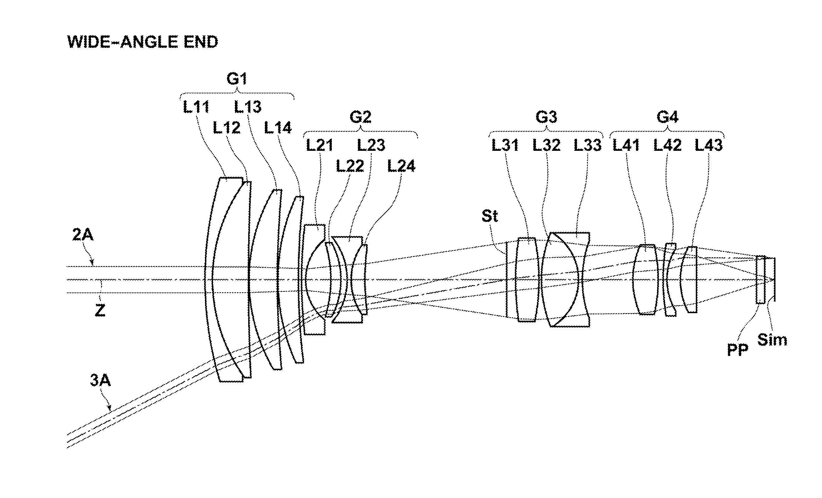
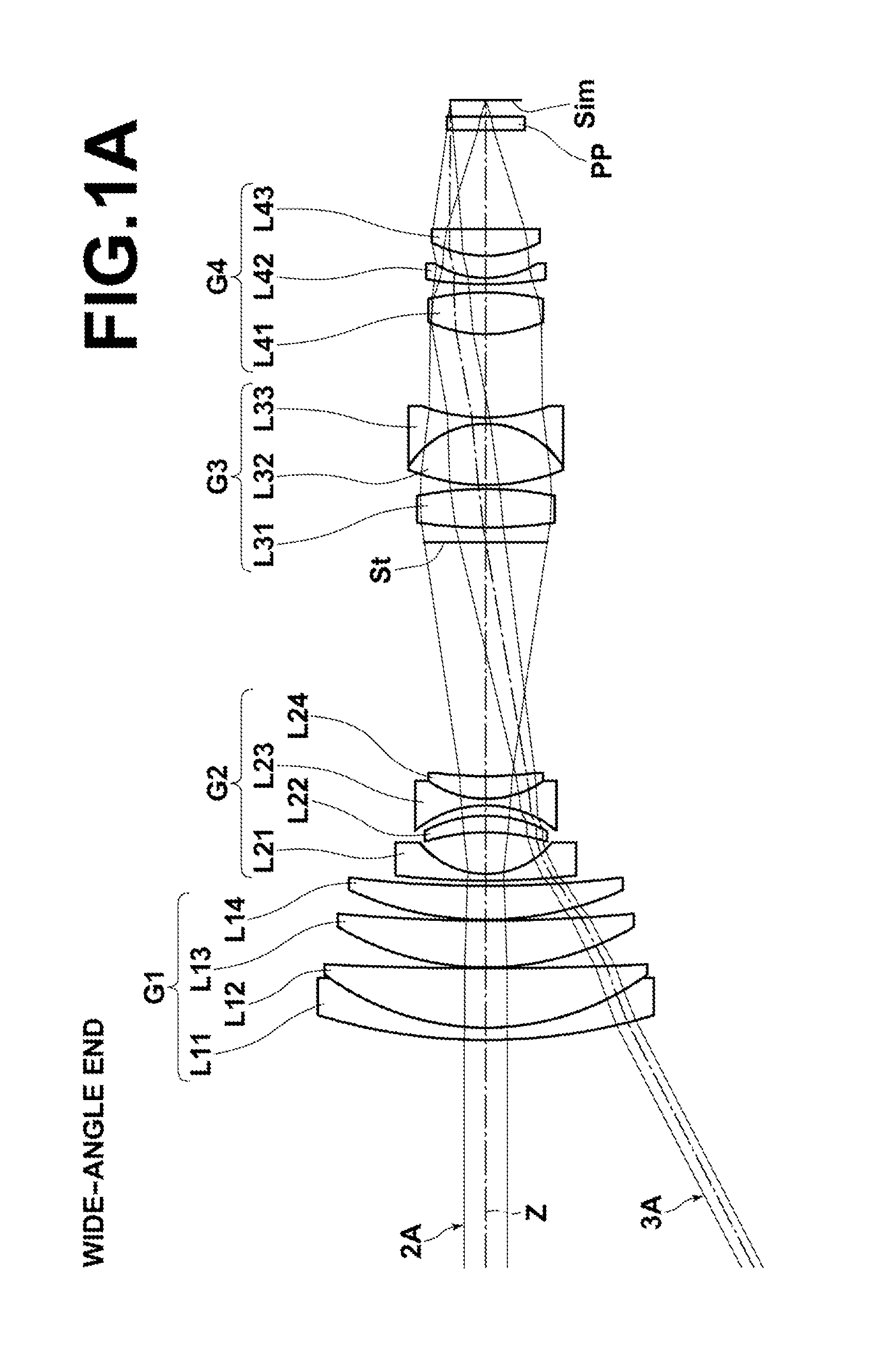
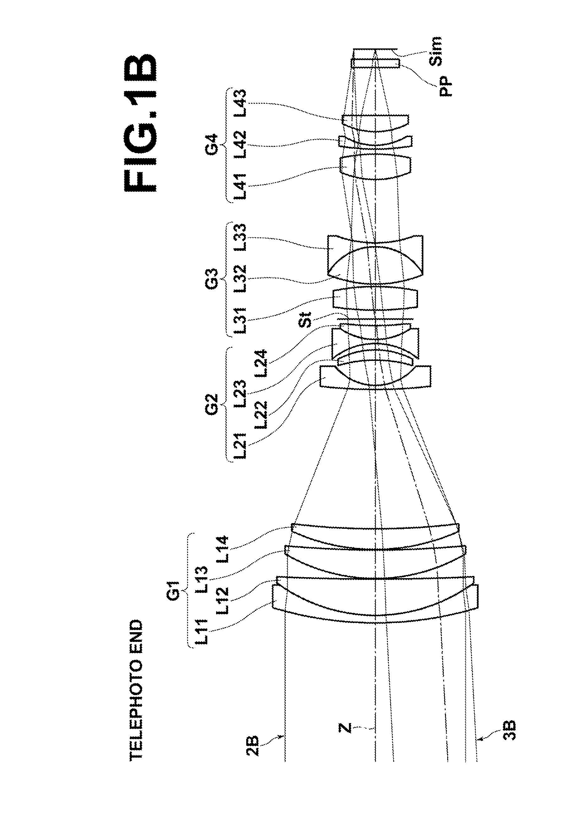
[0067]Hereinafter, embodiments of the present invention will be described with reference to drawings. FIGS. 1A and 1B are cross sections illustrating a structure example of a variable magnification optical system according to an embodiment of the present invention. FIGS. 1A and 1B illustrate the arrangement of lenses at a wide-angle end and at a telephoto end, respectively, when the optical system is focused on an object at infinity, and they correspond to a variable magnification optical system in Example 1, which will be described later. In FIGS. 1A and 1B, the left side is the object side, and the right side is the image side. In both of the cross sections in FIG. 1A and FIG. 1B, axial rays 2A, 2B and off-axial rays 3A, 3B at a maximum angle of view are also illustrated.

[0068]The variable magnification optical system includes, along optical axis Z, first lens group G1 having positive refractive power, second lens group G2 having negative refractive power, aperture stop St, third ...


PUM


Abstract

A variable magnification optical system includes a positive first lens group, a negative second lens group, a stop, a positive third lens group and a positive fourth lens group, which are in this order from an object side. The first lens group, the stop and the third lens group are fixed, but the second lens group and the fourth lens group move in an optical axis direction during magnification change. The fourth lens group has a focusing function. The third lens group includes at least an aspherical surface, and consists of, in the following order from the object side, a positive lens and a cemented lens of a positive lens and a double-concave lens cemented together. The variable magnification optical system satisfies a predetermined formula.

Description

BACKGROUND OF THE INVENTION[0001]1. Field of the Invention[0002]The present invention relates to a variable magnification optical system used in a video camera, an electronic still camera or the like, and an imaging apparatus. In particular, the present invention relates to a variable magnification optical system that is especially appropriate for a surveillance camera, and which can be used both in a visible wavelength band and in a near-infrared wavelength band, and an imaging apparatus including the variable magnification optical system.[0003]2. Description of the Related Art[0004]Conventionally, a variable magnification optical system for CCTV (Closed-circuit Television) has been developed, as an optical system used in an imaging apparatus, such as a video camera, an electronic still camera and a surveillance camera, which uses an imaging device, such as a CCD (Charge Coupled Device) and a CMOS (Complementary Metal Oxide Semiconductor), as a recording medium. As such a variable ...

Claims


Application Information

Patent Timeline
IPC IPC(8): G02B15/14
CPCG02B15/14G02B3/04G02B15/144113
Inventor ONO, KAZUNORI
Owner FUJIFILM CORP
Why Eureka
Try Eureka