

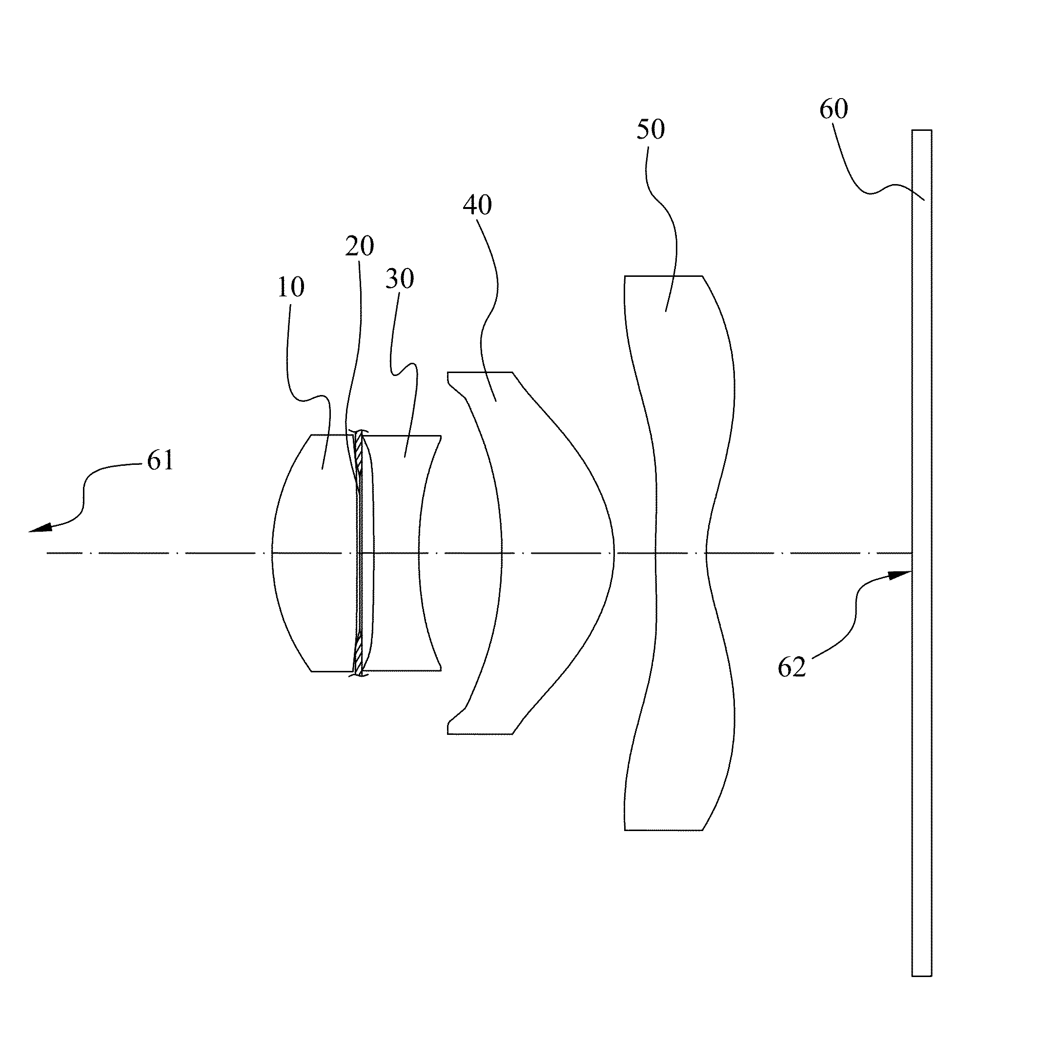
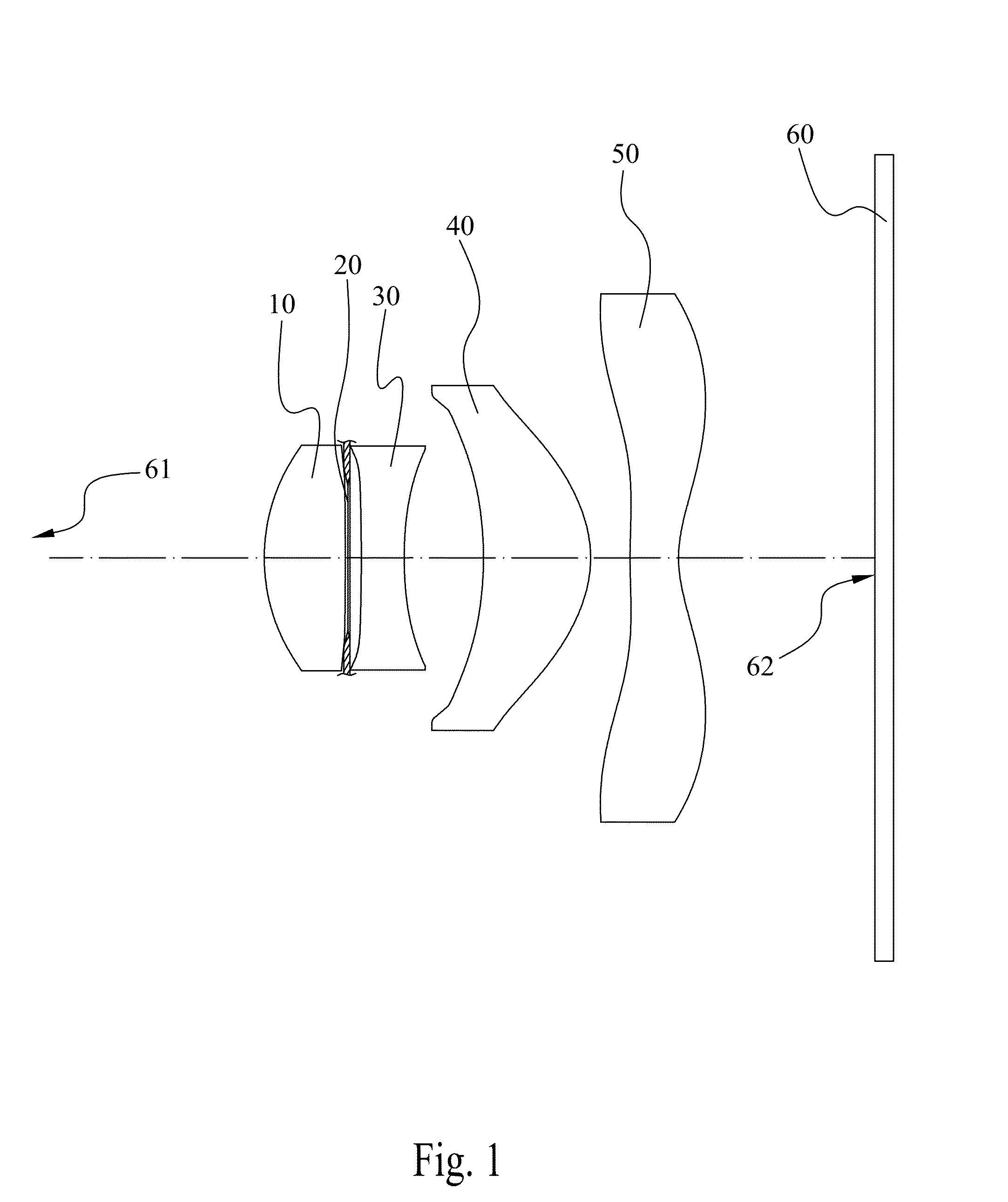
Imaging lens apparatus
a technology of imaging lens and lens body, which is applied in the field of imaging lens body, can solve the problems of reduced reflect inability to completely eliminate flare and ghost, and inability to reduce the impact of the lens, so as to reduce ghost and flare formation, improve image quality, and limit the angle of incidence ray and irradiance of reflected ligh
- Summary
- Abstract
- Description
- Claims
- Application Information
AI Technical Summary
Benefits of technology
Problems solved by technology
Method used
Image

Examples
first embodiment
[0047]Referring to FIG. 3, FIG. 3 shows the In this embodiment, the F number is 2.8, angle of view is more than 69.8 degree, f / BFL is 2.93, f2 / f is −1.8, R3 / f is −3.25, and the radius of curvature, value of air space, refractivity and abbe number are listed below:
Radius ofsurface #curvatureAir spaceRefractivityAbbe numberS11.3330.5481.531155.7stop−13.0020.122S3−7.8600.3001.585030.0S42.8700.578S5−2.6740.7561.531155.7S6−0.8890.340S74.9370.3091.531155.7S80.9020.317S9Inf0.1451.517064.1S10Inf0.626
[0048]Furthermore, the aspheric surfaces of the first lens 10 to the fourth lens 50 satisfy the following aspheric equation:
z=ch21+(1-(1+k)c2h2)+A4h4+A6h6+A8h8+A10h10+A12h12+A14h14+A16h16
[0049]Wherein, c is the curvature of the lens surface, h is the vertical distance between the surface of lens and the optical axis, k is the conic constant, and A4, A6, A8, A10, A12, A14 and A16 are the aspheric constants of the higher order items. Said conic constant and aspheric constants are listed below:
S1S...
second embodiment
[0052]Referring to FIG. 5, FIG. 5 shows the In this embodiment, the F number is 2.8, angle of view is more than 74.6 degree, f / BFL is 2.88, f2 / f is −1.64, R3 / f is −3.15, and the radius of curvature, value of air space, refractivity and abbe number are listed below:
Radius ofsurface #curvatureAir spaceRefractivityAbbe numberS11.3020.5561.531155.7stop22.8240.101S3−9.6700.2851.585030.0S44.3400.551S5−2.0810.8111.544156.0S6−0.8030.281S72.6460.3351.531155.7S80.7370.317S9Inf0.1451.51764.1S10Inf0.604
[0053]Furthermore, the aspheric surfaces of the first lens 10 to the fourth lens 50 satisfy the following aspheric equation:
z=ch21+(1-(1+k)c2h2)+A4h4+A6h6+A8h8+A10h10+A12h12+A14h14+A16h16
[0054]Wherein, c is the curvature of the lens surface, h is the vertical distance between the surface of lens and the optical axis, k is the conic constant, and A4, A6, A8, A10, A12, A14 and A16 are the aspheric constants of the higher order items. Said conic constant and aspheric constants are listed below:
S1S2...
third embodiment
[0057]Referring to FIG. 7, FIG. 7 shows the In this embodiment, the F number is 2.8, angle of view is more than 69.4 degree, f / BFL is 3.16, f2 / f is −1.03, R3 / f is −1.76, and the radius of curvature, value of air space, refractivity and abbe number are listed below:
Radius ofsurface #curvatureAir spaceRefractivityAbbe numberS11.3840.4921.531155.7stop−8.1400.144S3−6.0040.3191.585030.0S43.2130.589S5−2.9310.7691.531155.7S6−0.9340.300S75.4770.3821.531155.7S80.9100.317S9inf0.1451.5170664.1S10inf0.615
[0058]Furthermore, the aspheric surfaces of the first lens 10 to the fourth lens 50 satisfy the following aspheric equation:
z=ch21+(1-(1+k)c2h2)+A4h4+A6h6+A8h8+A10h10+A12h12+A14h14+A16h16
[0059]Wherein, c is the curvature of the lens surface, h is the vertical distance between the surface of lens and the optical axis, k is the conic constant, and A4, A6, A8, A10, A12, A14 and A16 are the aspheric constants of the higher order items. Said conic constant and aspheric constants are listed below:
S1...
PUM
 Abstract
Description
Claims
Application Information