
Light-emitting apparatus, illumination system, vehicle headlamp, projector, and method for manufacturing light-emitting apparatus

Active Publication Date: 2013-12-19
SHARP FUKUYAMA LASER CO LTD
View PDF8 Cites 54 Cited by
  • Summary
  • Abstract
  • Description
  • Claims
  • Application Information

AI Technical Summary

Benefits of technology

The present invention provides a light-emitting apparatus that can efficiently dissipate heat generated by a light emitter. This is achieved by microscopic surface irregularities on the light-emitting element and heat-conducting member that form a relatively large gap between them, reducing the efficiency of heat conduction.

Problems solved by technology

However, if the heat-conducting member is formed independently of the light-emitting element and is brought into contact with the surface of the light-emitting element, the heat generated by the light-emitting element cannot be efficiently conducted to the heat-conducting member.
Specifically, the light-emitting element and the heat-conducting member have microscopic surface irregularities, which form a relatively large gap therebetween when they are brought into contact with each other.
This gap decreases the efficiency of heat conduction from the light-emitting element to the heat-conducting member and thus prevents efficient dissipation of the heat generated by the light-emitting element.
Bonding the light-emitting element and the heat-conducting member with an organic resin, however, has the following new problem.

Method used


Image

  • Light-emitting apparatus, illumination system, vehicle headlamp, projector, and method for manufacturing light-emitting apparatus
  • Light-emitting apparatus, illumination system, vehicle headlamp, projector, and method for manufacturing light-emitting apparatus
  • Light-emitting apparatus, illumination system, vehicle headlamp, projector, and method for manufacturing light-emitting apparatus

Examples


first embodiment

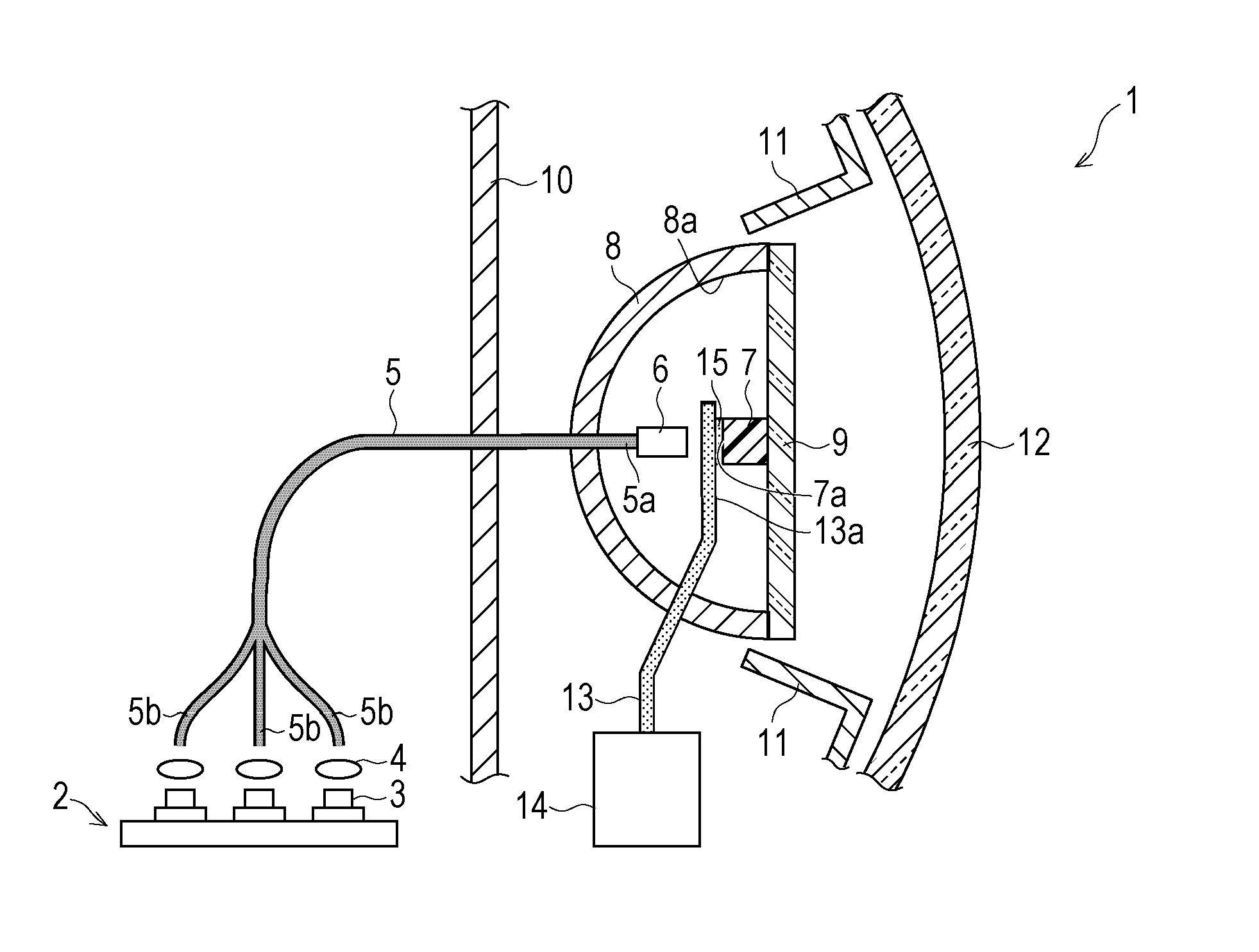
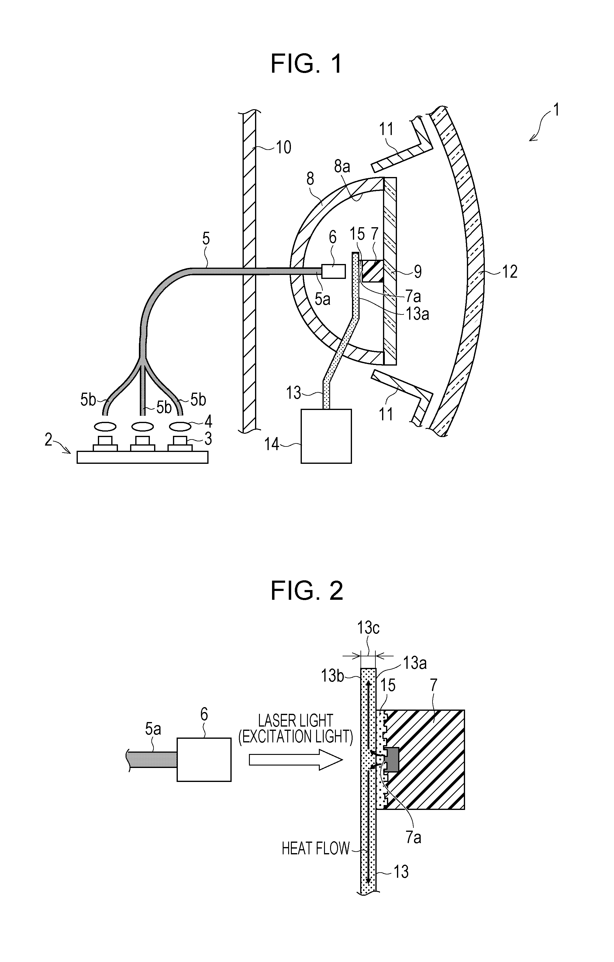
[0053]An embodiment of the present invention will now be described with reference to FIGS. 1 to 5(d). This embodiment illustrates an automotive headlamp (vehicle headlamp) 1 as an example of an illumination system including a light-emitting apparatus according to the present invention.

[0054]It is to be understood, however, that the illumination system according to the present invention may also be implemented as headlamps for vehicles and moving objects other than automobiles (e.g., humans, ships, aircraft, submarines, and rockets) or as other illumination systems. Examples of such other illumination systems include searchlights, projectors, household lighting fixtures, indoor lighting fixtures, and outdoor lighting fixtures.

[0055]The headlamp 1 may comply with light distribution characteristics standards for main-beam headlamps (high beams) or light distribution characteristics standards for dipped-beam headlamps (low beams).

(Structure of Headlamp 1)

[0056]The structure of the headl...

second embodiment

[0203]Another embodiment of the present invention will now be described with reference to FIG. 6. The same components as in the first embodiment are indicated by the same reference signs, and a description thereof is omitted. This embodiment illustrates another example of the member that holds the light-emitting element 7 together with the heat-conducting member 13.

(Structure of Headlamp 30)

[0204]FIG. 6 is a sectional view showing the structure of a headlamp 30 according to this embodiment. As shown in FIG. 6, the headlamp 30 includes a transparent plate 18, a metallic ring 19, a reflective mirror 81, a substrate 82, and screws 83. The light-emitting element 7 of the headlamp 30 is held between the heat-conducting member 13 and the transparent plate 18.

[0205]The reflective mirror 81 has the same function as the reflective mirror 8 and is shaped to be cut in a plane perpendicular to the optical axis near the focal position thereof. The reflective mirror 81 may be formed of any materi...

third embodiment

[0219]Another embodiment of the present invention will now be described with reference to FIGS. 7 to 11. The same components as in the first embodiment are indicated by the same reference signs, and a description thereof is omitted.

[0220]This embodiment illustrates an automotive headlamp (vehicle headlamp) 60 including a light-emitting element 17 having a composition with superior heat dissipation. In the following description, a structure of the automotive headlamp 60 in which no gap layer 15 according to the present invention is formed will be discussed first.

(Structure of Headlamp 60)

[0221]FIG. 8 is a sectional view showing the structure of the headlamp 60. As shown in FIG. 8, the headlamp 60 includes a semiconductor laser array 2, aspherical lenses 4, optical fibers 5, a ferrule 6, a light-emitting element (sintered light emitter) 17, a reflective mirror 8, a transparent plate 9, a housing 10, an extension 11, a lens 12, a heat-conducting member 13, and a cooling element 14.

(Lig...


PUM


Abstract

A headlamp (1) includes a semiconductor laser (3); a light-emitting element (7) that emits light in response to laser light emitted from the semiconductor laser (3); a heat-conducting member (13) that receives heat generated by the light-emitting element (7) through a light-emitting-element facing surface (13a); and a gap layer (15) that is disposed between the light-emitting element (7) and the light-emitting-element facing surface (13a) and that conducts the heat generated by the light-emitting element (7) to the light-emitting-element facing surface (13a). The gap layer (15) contains at least an inorganic amorphous material.

Description

REFERENCE TO RELATED APPLICATIONS[0001]This application is a national stage application under 35 USC 371 of International Application No. PCT / JP2012 / 055997, filed Mar. 8, 2012, which claims the priority from Japanese Patent Application Nos. 2011-050635, filed Mar. 8, 2011, and 2011-137842, filed Jun. 21, 2011, the entire contents of which are incorporated herein by reference.FIELD OF THE INVENTION[0002]The present invention relates to sintered light emitters that function as high-intensity light sources, to light-emitting apparatuses including such sintered light emitters, to illumination systems, vehicle headlamps, and projectors including such light-emitting apparatuses, to methods for fabricating sintered light emitters, and to methods for manufacturing light-emitting apparatuses.BACKGROUND OF THE INVENTION[0003]In recent years, extensive research has been directed to light-emitting apparatuses including a semiconductor light-emitting device, such as a light-emitting diode (LED) ...

Claims


Application Information

Patent Timeline
IPC IPC(8): F21V29/00B60Q1/04G03B21/14F21V9/00
CPCF21V29/2293F21V9/00B60Q1/04G03B21/14Y10S977/95B82Y20/00F21S8/04F21V7/22F21V29/70F21Y2115/10F21Y2115/30F21S41/16F21S41/176F21S41/24F21V9/30G02B6/0008G03B21/16G03B21/204H01S5/32341H01S5/4031H01S5/0087H01S5/02251
Inventor SATO, RINAKISHIMOTO, KATSUHIKO
Owner SHARP FUKUYAMA LASER CO LTD
Features
  • Generate Ideas
  • Intellectual Property
  • Life Sciences
  • Materials
  • Tech Scout
  • Unparalleled Data Quality
  • Higher Quality Content
  • 60% Fewer Hallucinations
Learn More