Embossing Press

a technology of embossing press and embossing tool, which is applied in the direction of press ram, dough shaping, manufacturing tools, etc., can solve the problems of achieving quality formation of microscale features at a sufficient rate, and the method of hot embossing is not widely used, so as to achieve micron-level precision and simple design , the effect of reducing the cos

Inactive Publication Date: 2013-12-19
MASSACHUSETTS INST OF TECH
View PDF20 Cites 4 Cited by
  • Summary
  • Abstract
  • Description
  • Claims
  • Application Information

AI Technical Summary

Benefits of technology

[0009]The embossing press design disclosed herein offers several advantages over existing methods. The embossing press of the invention is designed to maintain micron-level precision during the embossing process that is simple in design and significantly lower in cost than competing systems. The press according to the invention is highly compact and presents a much smaller form factor than competing devices while still offering more than sufficient force and temperature capabilities necessary to emboss, for example, a 25 mm by 25 mm polymer substrate. The invention is also capable of micron-level repeatability. Utilizing passive kinematic alignment features and precise, completely linear motion, the embossing press of the invention achieves precision and repeatability of forming on the micron level using relatively simple structures. The system is capable of rapid heating and cooling cycles due to low thermal mass of its forming platens. The rapid heating and cooling enables low cycle times for producing single parts.
[0010]An important aspect of the present design is that it can be scaled for different sized products. For example, the design can be scaled up to emboss a 55 mm by 85 mm polymer substrate (credit card size) or larger using the design disclosed herein but with suitably adjusted dimensions to allow for economical “right sizing” of the embossing press.

Problems solved by technology

However, producing microscale parts by hot embossing is a method currently not commonly employed on an industrial scale.
Achieving quality formation of microscale features at a sufficient rate has been a major difficulty.

Method used


Image

  • Embossing Press
  • Embossing Press
  • Embossing Press

Examples


Embodiment Construction

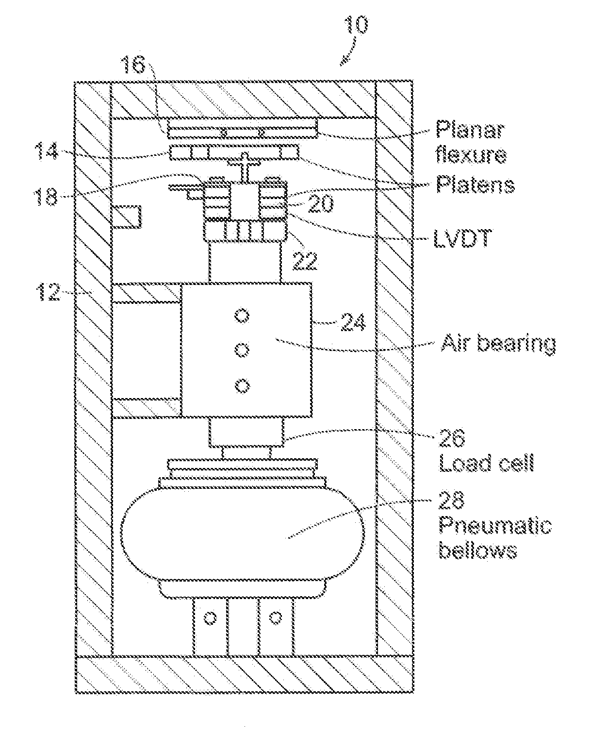
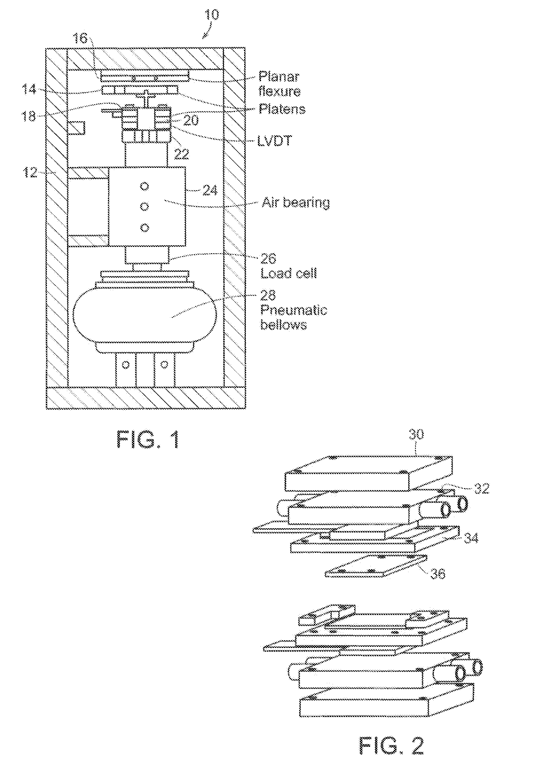
[0015]With reference first to FIG. 1 an embossing press 10 includes a box frame structure 12. The box frame 12 provides superior deflection and thermal performance while being smaller and lighter than other comparable designs.

[0016]During embossing, a load most be applied to material compressed between two platens while maintaining parallelism between the platens. In a preferred embodiment, the box frame 12 is designed to deflect less than 5 microns per 1,000 newtons of loading force. Because of the symmetry of the box frame 12, any deformation has no parasitic angular component that will affect platen alignment.

[0017]The embossing press 10 must also sustain large changes in temperature during embossing and de-molding cycles. The symmetry of the box frame 12 ensures that any deformation due to thermal gradients is manifest as a linear translation between the platens and not a change in parallelism. In a preferred embodiment, the box frame 12 is constructed of aluminum plates and may...


PUM

PropertyMeasurementUnit
loading forceaaaaaaaaaa
forceaaaaaaaaaa
sizeaaaaaaaaaa

Abstract

Precision embossing press. The press includes a rigid symmetric box frame and upper and lower parallel embossing platens mounted within the box frame for movement towards one another to provide an embossing compressive force on a work piece between the platens while maintaining parallelism between the platens. A thermal system controls platen temperature to heat the work piece for embossing and to cool the work piece for de-molding. A pneumatic actuator moves the lower platen toward the upper platen to emboss the work piece. A closed loop control system employing feedback and feed forward control loops controls platen temperatures and embossing force.

Description

[0001]This application claims priority to provisional application Ser. No. 61 / 659,665 filed on Jun. 14, 2012, the contents of which are incorporated herein by reference in their entirety.BACKGROUND OF THE INVENTION[0002]This invention relates to an embossing press and more particularly to a precision embossing press that can be constructed from common an inexpensive mechanical elements, but that provides high resolution motion, loading and sensing with high bandwidth thermal actuation.[0003]Polymer embossing can be used to form surface geometry in polymer work pieces. However, producing microscale parts by hot embossing is a method currently not commonly employed on an industrial scale. Achieving quality formation of microscale features at a sufficient rate has been a major difficulty. In microfluidic applications, however, embossing has been a viable manufacturing process for moderate product volumes in comparison to injection molding.[0004]A hot embossing process utilizes three pr...

Claims


Application Information

Patent Timeline
Patent Type & Authority Applications(United States)
IPC IPC(8): B29C59/02
CPCB29C59/02B30B1/003B30B15/007B30B15/064
Inventor HARDT, DAVID E.BAGEANT, MAIA REYNOLDSPETRZELKA, JOSEPH EDWARD
Owner MASSACHUSETTS INST OF TECH
Why Eureka
Try Eureka