Electronically controlled high-frequency jet ventilation laryngoscope

a high-frequency jet and laryngoscope technology, applied in the field of high-frequency jet ventilation laryngoscopes, can solve the problems of insufficient achievement, inconvenient operation for operators, and inability to perform trachea intubation in on-site cardiopulmonary resuscitation, and achieve the effect of accurate and reliable use, easy operation and convenient operation

Active Publication Date: 2013-12-19
SHANDONG YIHE MEDICAL TECH
View PDF3 Cites 9 Cited by
  • Summary
  • Abstract
  • Description
  • Claims
  • Application Information

AI Technical Summary

Benefits of technology

[0014]The advantages of the present invention include: The oxygen supply is carried out by high-frequency jet ventilation through an electronic automatic control process during the intubation of human lung resuscitation trachea. At the same time, the cardiopulmonary resuscitation drug can be injected into the body for prompt treatment of critical patients. The self-powered laryngoscope is compact and flexible, portable, easy to operate as well as accurate and reliable to use. Thus, it is suitable to a variety of on-site resuscitation situations involving patient manoeuvring.

Problems solved by technology

The fact that this first type of laryngoscope must be used in conjunction with a high-frequency ventilator renders it inflexible, and the laryngoscope is not suitable for the trachea intubation in on-site cardiopulmonary resuscitation.
Typically, the highest frequency of manual control achievable is about 30 beats-per-minute, and is insufficient to achieve the generally acceptable high-frequency ventilation frequency of 110 beats-per-minute.
This procedure is difficult and inconvenient for the operator to perform and, even with an operator having a high degree of hand-eye coordination, the procedure is not considered an efficient patient treatment method.

Method used


Image

  • Electronically controlled high-frequency jet ventilation laryngoscope
  • Electronically controlled high-frequency jet ventilation laryngoscope
  • Electronically controlled high-frequency jet ventilation laryngoscope

Examples


embodiment 1

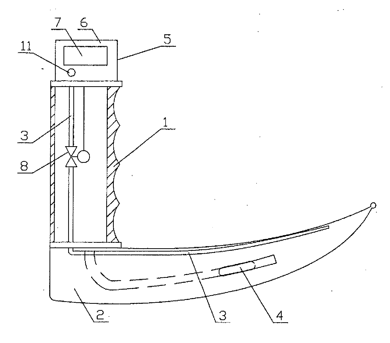
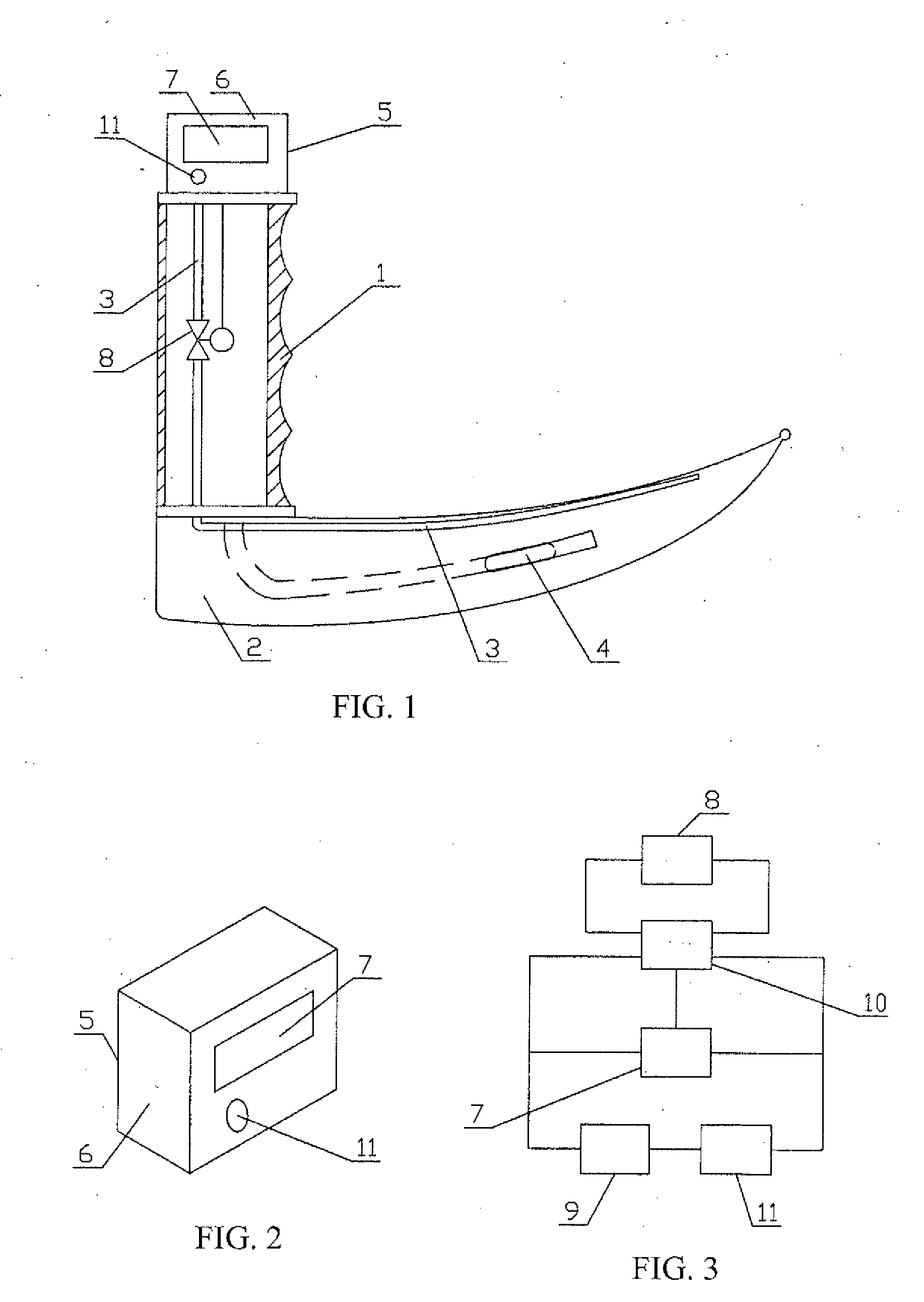
[0027]Referring to FIGS. 1 to 3, there is shown an electronically controlled high-frequency jet ventilation laryngoscope according to a first embodiment. The laryngoscope includes a laryngoscope handle 1 and a laryngoscope blade 2. The laryngoscope handle 1 and the laryngoscope blade 2 form an integral structure. An oxygen supply tube 3 is disposed within the laryngoscope handle 1. A front-end of the oxygen supply tube 3 is placed on the front end of the laryngoscope blade 2; and lamp beads 4 are located on the front-end of the laryngoscope blade 2.

[0028]The laryngoscope also includes an electronic controller 5 which consists of a shell body 6, a display screen 7, a solenoid valve 8, a power supply module 9, a control module 10 and a control switch 11. The shell body 6 is fixed to the top of the laryngoscope handle 1. The display screen 7 and the control switch 11 are located on the shell body 6, while the power supply module 9, and the control module 10 are both disposed within the...

embodiment 2

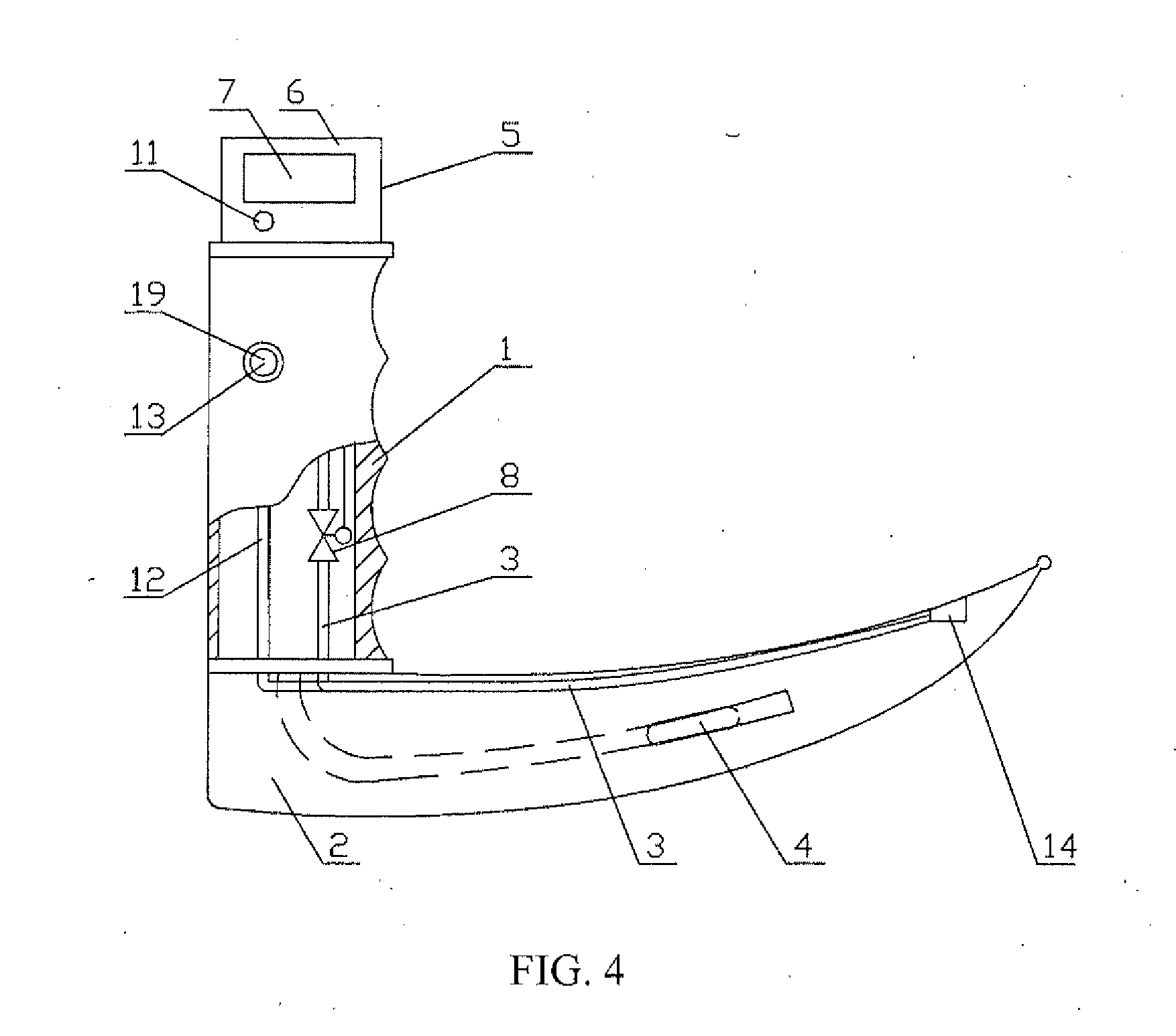
[0030]Referring to FIG. 4, there is shown an electronically controlled high-frequency jet ventilation laryngoscope according to a second embodiment. The laryngoscope includes a laryngoscope handle 1, laryngoscope blade 2, oxygen supply tube 3, lamp beads 4, electronic controller 5, shell body 6, display screen 7, solenoid valve 8, power supply module 9, control module 10 and control switch 11. The position and function of these elements is the same as that described in relation to Embodiment 1 above.

[0031]The laryngoscope of Embodiment 2 also includes a drug-administrating tube 12, a drug-administrating control valve 13, a spray orifice 14, and a drug-administrating manual control valve 19. The drug-administrating tube 12 is disposed within laryngoscope handle 1, while the drug-administrating control valve 13 is disposed within the drug-administrating tube 12. The drug-administrating control valve 13 is a drug-administrating manual control valve 19 and is located on the shell of the...

embodiment 3

[0034]Referring now to FIG. 5 and FIG. 6, there is shown an electronically controlled high-frequency jet ventilation laryngoscope according to a third embodiment. The laryngoscope of Embodiment 3 includes laryngoscope handle 1, laryngoscope blade 2, oxygen supply tube 3, lamp beads 4, electronic controller 5, shell body 6, display screen 7, solenoid valve 8, power supply module 9, control module 10, control switch 11, drug-administrating tube 12, drug-administrating control valve 13, spray orifice 14, and drug-administrating solenoid valve 20 common to previous embodiments. In Embodiment 3, the drug-administrating manual valve 19 in Embodiment 2 is replaced by the drug-administrating electromagnetic valve 20 and their connection structure is the same as that of the Embodiment 2. That is, the control module 10 is connected with the drug-administrating solenoid valve 20 and the control module 10 controls the working frequency of the drug-administrating solenoid valve 18.

[0035]The lary...


PUM


Abstract

An electronically controlled high frequency jet ventilation laryngoscope includes a laryngoscope handle and a laryngoscope blade. An oxygen supply tube is set within the laryngoscope handle and the front end of oxygen supply tube is placed on the front end of the laryngoscope blade. The laryngoscope also includes an electronic controller having a shell body, a display screen, a solenoid valve, a power supply module, a control module and a control switch. The shell body is fixed at the top of the laryngoscope handle; the display screen and control switch are on the shell body; the power supply module and control module are within the shell body; the solenoid valve is on the oxygen supply tube within the laryngoscope handle; the display screen, control module and control switch are connected with the power supply module; and the control module is connected with the display screen and the solenoid valve, respectively.

Description

FIELD OF TECHNOLOGY[0001]The present invention relates to high frequency jet ventilation laryngoscopes and in particular to an electronically controlled high frequency jet ventilation laryngoscope, in the field of medical devices.BACKGROUND OF TECHNOLOGY[0002]Currently there are two main types of jet ventilation laryngoscope that are sold and used in the market. Both of these types of laryngoscope have different functions. A first type of laryngoscope must be used in conjunction with a high-frequency jet ventilator during the intubation process. In this process, the oxygen supply to the body is carried out with a pulse generated by the high-frequency jet ventilator through ventilation of the jet laryngoscope. The fact that this first type of laryngoscope must be used in conjunction with a high-frequency ventilator renders it inflexible, and the laryngoscope is not suitable for the trachea intubation in on-site cardiopulmonary resuscitation.[0003]The second main type of laryngoscope ...

Claims


Application Information

Patent Timeline
Patent Type & Authority Applications(United States)
IPC IPC(8): A61B1/015A61B1/267
CPCA61B1/015A61B1/267A61B1/0676A61M16/0096A61M2202/0208A61M2205/502A61B1/00066A61M16/021
Inventor WU, DA
Owner SHANDONG YIHE MEDICAL TECH
Why Eureka
Try Eureka