
Automatic drive navigation system

a technology of automatic driving and navigation system, applied in the direction of electric digital data processing, instruments, computing, etc., can solve the problems of requiring a large amount of cost, not being able to selectively acquire desired driving information alone, and not being able to achieve the effect of low cos

Inactive Publication Date: 2013-12-19
RICOH KK
View PDF1 Cites 42 Cited by
  • Summary
  • Abstract
  • Description
  • Claims
  • Application Information

AI Technical Summary

Benefits of technology

The present invention provides an automatic drive navigation system that can access driving information of an autonomous vehicle from anywhere, without being restricted by position. The system allows operators to set which driving information is being notified to them. The system also allows multiple autonomous vehicles to be remotely controlled simultaneously. Additionally, the system is cost-effective, works with PCs, and operates in LAN environments.

Problems solved by technology

Moreover, the operator cannot selectively acquire desired driving information alone among various types of information such as destination, driving position or status, carrying objects, and anomaly of the vehicle.
With the system disclosed in Reference 3 it is not possible to call out the automatic guided vehicle to an arbitrary position or stop point from an arbitrary calling device, and perform the vehicle callout while checking the current positions of all the automatic guided vehicles.
Further, the calling devices and automatic guided vehicles are connected via a dedicated wireless LAN (Local Area Network), which takes a larger amount of costs and imposes a large load for installing the system or relocating it with a change in layout.
Particularly, in the system disclosed in Reference 4 an operator inputs a destination to a personal computer (PC) mounted in the autonomous vehicle so that it is not possible to call out the automatic guided vehicle to an arbitrary position or stop point from an arbitrary calling device, and perform the vehicle callout while checking the current positions of all the automatic guided vehicles, either.

Method used


Image

  • Automatic drive navigation system
  • Automatic drive navigation system
  • Automatic drive navigation system

Examples


Embodiment Construction

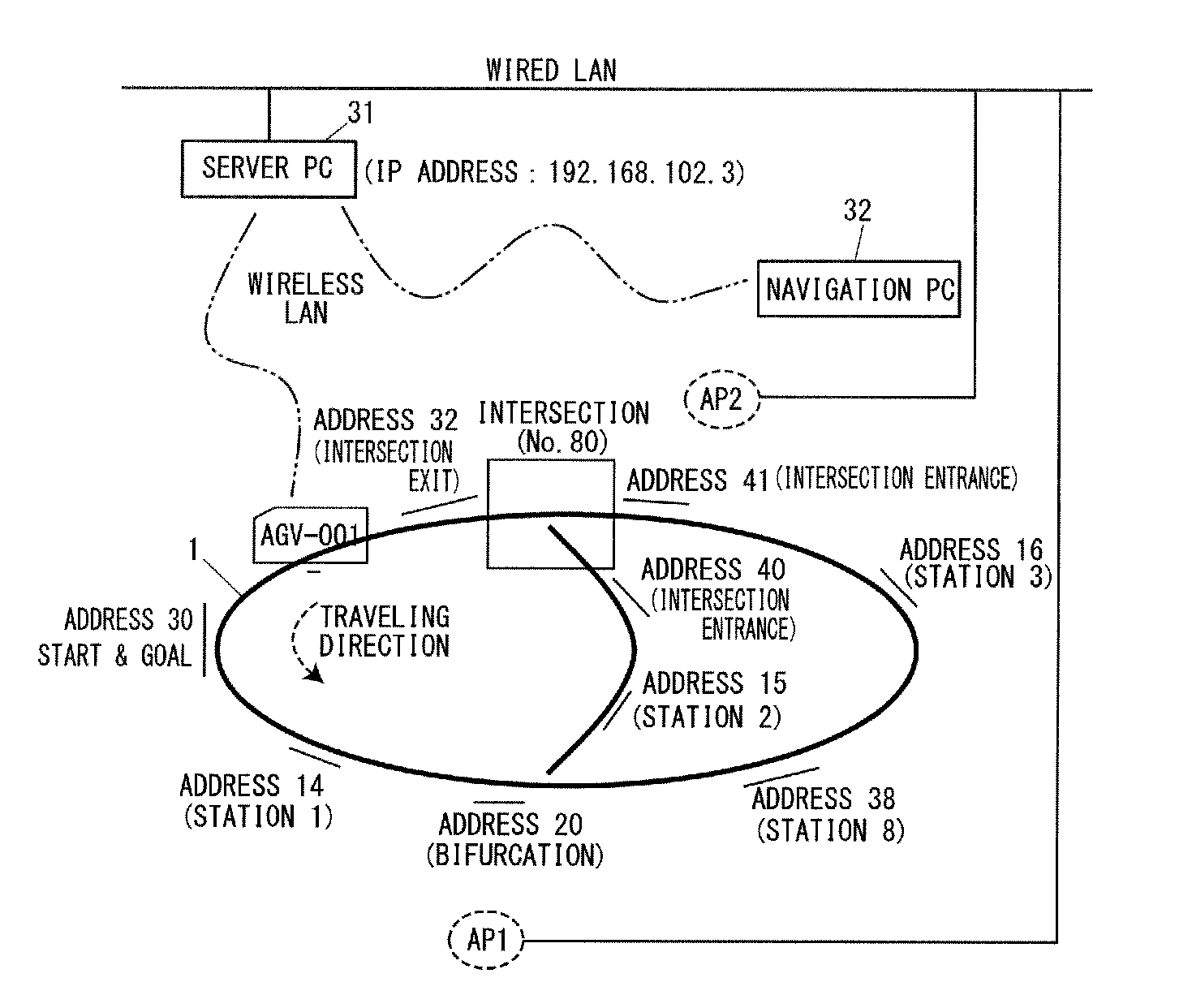
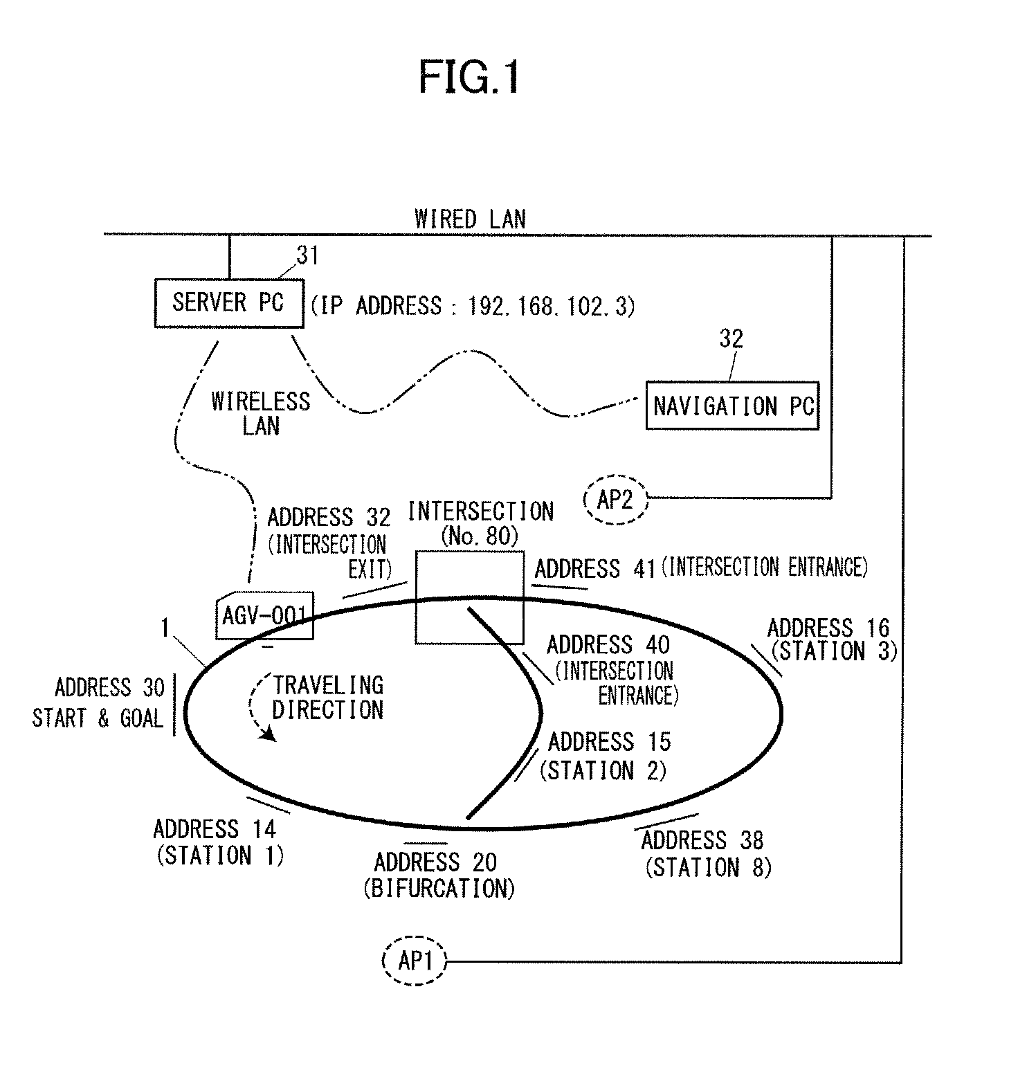
[0039]According to one embodiment of the present invention, the driving state of an autonomous vehicle AGV is notified to a navigation PC 32 as a navigation terminal, referring to an event table, if the driving state matches a condition set in the event table. This achieves the following effects:

[0040]The operator does not need to constantly pay attention to the navigation display of the navigation PC 32;

[0041]The operator can know only desired notification conditions such as arrival at designated station and occurrence of specified errors;

[0042]By issuing a pre-arrival audio notification, for example, when the vehicle comes at an address one before the station, workers can perform preparatory work in advance and process main operation efficiently;

[0043]A loss of time resulting from overlooking the arrival of a vehicle at station or occurrence of errors can be reduced;

[0044]The operator can concurrently select one or more of a rotary beacon light or a beeper, and an e-mail for an au...


PUM


Abstract

An automatic drive navigation system includes a navigation terminal having a display, to issue, to a server, a drive request for an autonomous vehicle input by an operator via a LAN communication, the server to hold the drive request, and the autonomous vehicle to start driving upon receipt of the drive request from the server, recognize a spot sign on a driving route, and automatically operate a self-driving system in accordance with the spot sign, wherein the navigation terminal, server, and autonomous vehicle are connected via a LAN and the autonomous vehicle notifies the server of driving information about the autonomous vehicle via the LAN communication, the server holds the notified driving information, and the navigation terminal accesses the server via the LAN communication to display the driving information on the display.

Description

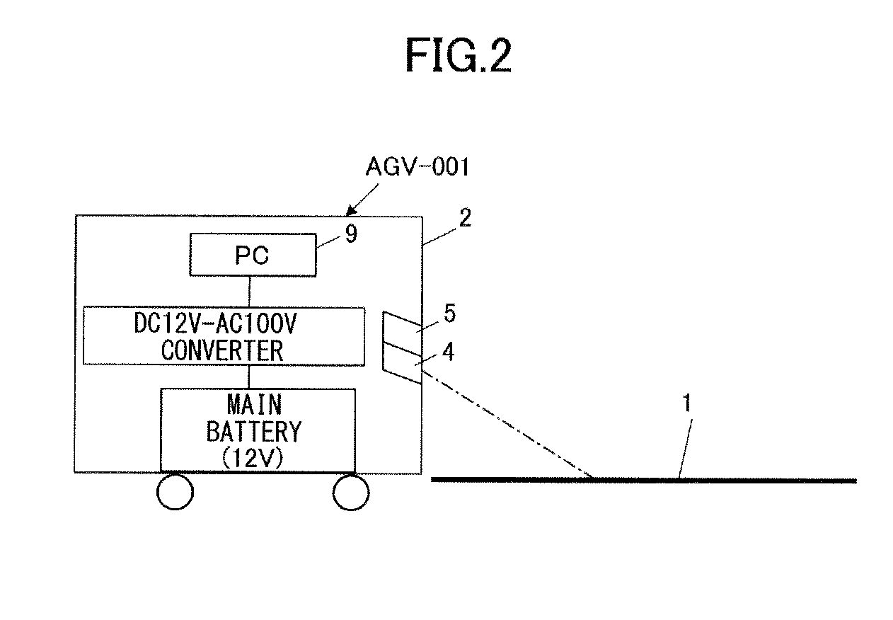
CROSS REFERENCE TO RELATED APPLICATION[0001]The present application is based on and claims priority from Japanese Patent Application No. 2012-138051, filed on Jun. 19, 2012, the disclosure of which is hereby incorporated by reference in its entirety.BACKGROUND OF THE INVENTION[0002]1. Field of the Invention[0003]The present invention relates to a navigation system to remotely operate an autonomous vehicle which has a self-drive system while monitoring the driving situation thereof. In particular, it relates to a navigation system to operate an autonomous vehicle relating to destinations, driving positions, driving status, recognition of carrying objects, status notification, or remote control. This system captures an image of a line marking on a floor surface with a camera and detects the relative position and posture of the line marking to the camera by image recognition to control the autonomous vehicle on the basis of the detected position and posture to drive along the line mark...

Claims


Application Information

Patent Timeline
IPC IPC(8): G05D1/00
CPCG05D1/0011G05D1/0022G05D1/0246
Inventor YAMAMOTO, SHOJI
Owner RICOH KK
Learn More