
Injector system

a technology of injectors and injectors, which is applied in the direction of liquid fuel feeders, machines/engines, mechanical apparatus, etc., can solve the problems of low quality, low cost efficiency of retrofit kits, and mainly fall short of the quality which is particularly necessary in emerging countries, and achieves the effect of high quality and higher quality

Inactive Publication Date: 2013-12-26
ROBERT BOSCH GMBH
View PDF22 Cites 4 Cited by
  • Summary
  • Abstract
  • Description
  • Claims
  • Application Information

AI Technical Summary

Benefits of technology

This patent describes an injector system that can be used in various types of internal combustion engines. The system is designed to be compact, easy to install and retrofit, and high-quality. It can be connected to the engine through flexible hose connections, making it adaptable to different engine designs. The injectors are installed without direct contact with the counter bracket, reducing wear and tear. The system is also connected to the fuel distribution rail using separate connecting elements, making installation and retrofitting easier. The fuel distribution rail is made of stainless steel or aluminum extrusion profiles, which makes it resistant to pressure and cost-effective. Overall, this injector system offers a wide range of applications and is easy to install and retrofit.

Problems solved by technology

Cost-effective retrofit kits for motor vehicles, which are driven by gasoline and which retrofit these for a CNG operation, mostly fall short of the quality which is particularly necessary for emerging countries.

Method used


Image

  • Injector system
  • Injector system
  • Injector system

Examples


Embodiment Construction

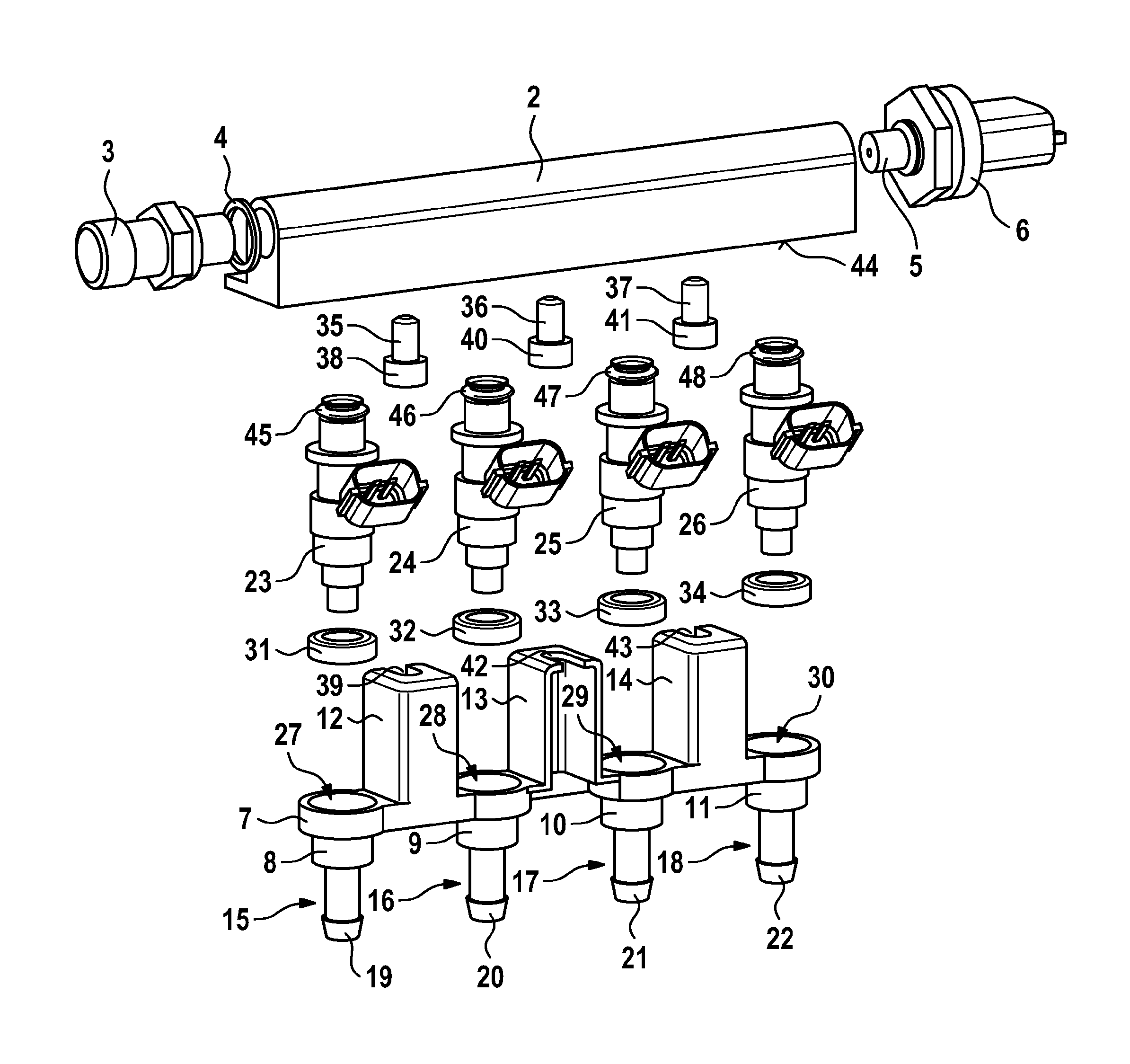
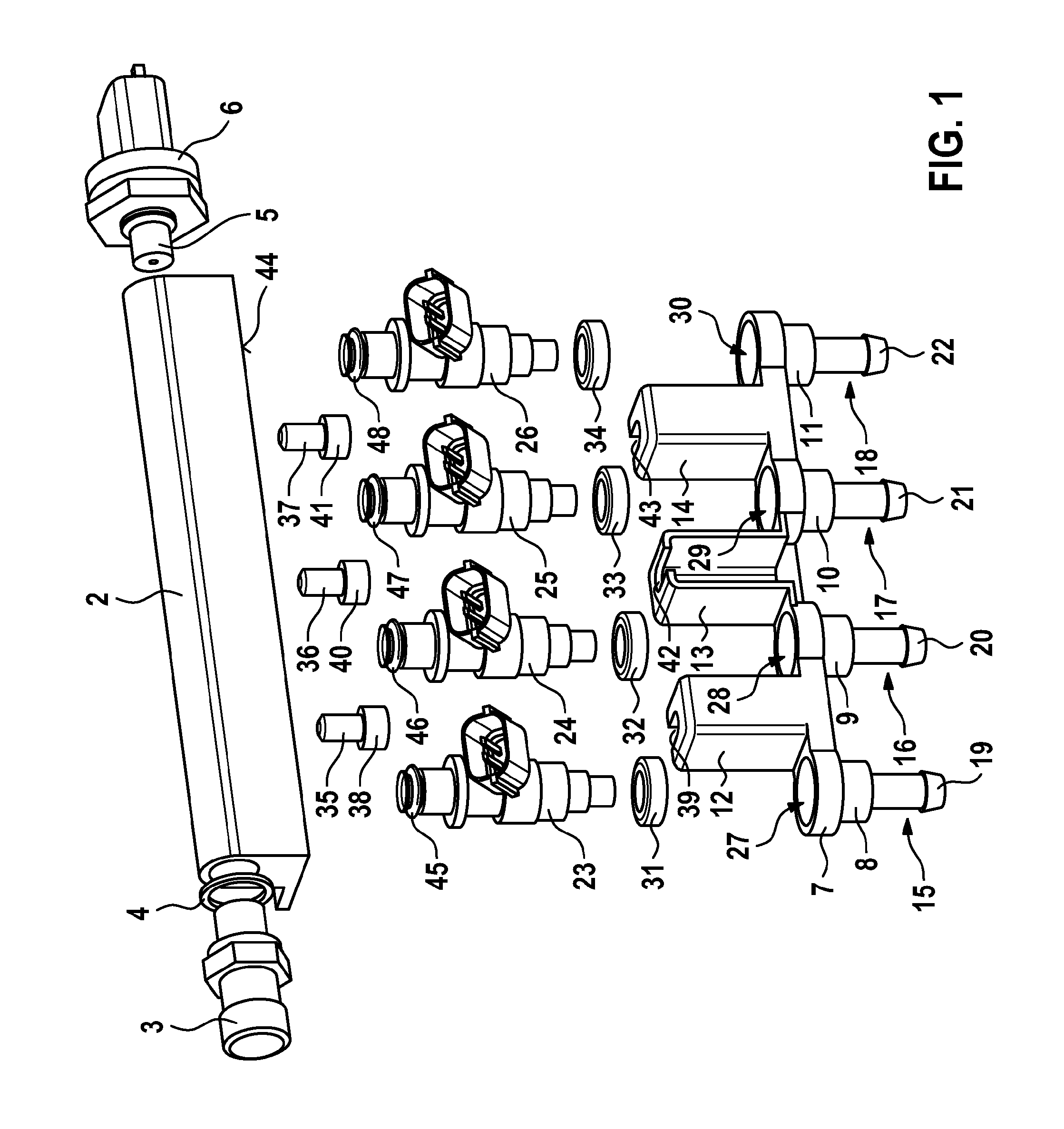
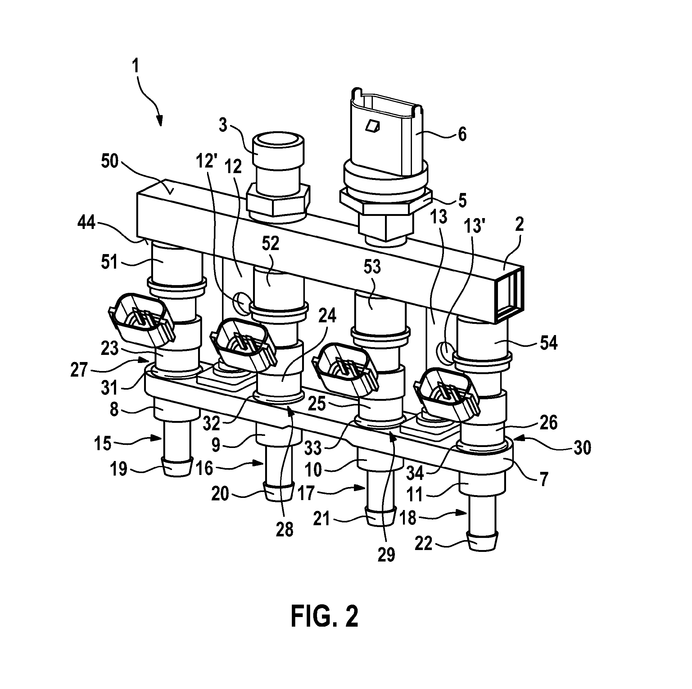
[0017]FIG. 1 shows an injector system 1 in a spatial exploded view according to one first exemplary embodiment. Injector system 1 may, in particular, be used as injector block 1 for fuel injection systems of mixture-compressing, spark-ignited internal combustion engines. Injector system 1 has a fuel distribution rail 2 which may be made of a metallic material, in particular aluminum. In particular, fuel distribution rail 2 may be designed as an extrusion profile. A connecting piece 3 is installed on fuel distribution rail 2. Here, a sealing ring 4 is provided which is situated between connecting piece 3 and fuel distribution rail 2. A fuel tank may, for example, be connected to connecting piece 3 via a piping. The fuel tank may, in this case, be used for storing natural gas, in particular compressed natural gas (CNG). Compressed natural gas is then conducted to fuel distribution rail 2 via connecting piece 3. Furthermore, a sensor 5 is installed on fuel distribution rail 2, a connec...


PUM


Abstract

An injector system which is in particular used as an injector block for fuel injection systems of mixture-compressing, spark-ignited internal combustion engines includes a fuel distribution rail, a counter bracket, a first injector, and at least one second injector. Here, the counter bracket has a first connecting piece and a second connecting piece. The first injector is joined to the counter bracket on an input side of the first connecting piece with the aid of an elastic sealing ring. The second injector is joined to the counter bracket on an input side of the second connecting piece with the aid of an elastic sealing ring. In this case, the counter bracket is connected to the fuel distribution rail. The fuel distribution rail is used for distributing compressed natural gas to the injectors. The injector system has a compact design.

Description

FIELD[0001]The present invention relates to an injector system, in particular an injector block, for fuel injection systems of mixture-compressing, spark-ignited internal combustion engines. Here, the injector system relates, in particular, to the distribution of natural gas for the internal combustion engine.BACKGROUND INFORMATION[0002]To supply natural gas, in particular compressed natural gas (CNG), systems are necessary which are adapted to the particular motor vehicle and in which appropriate openings for the installation of valves or fastening points for the holders of a fuel distribution rail are necessary on the corresponding intake module, for example. Thus, a vehicle-specific adaptation is necessary. Cost-effective retrofit kits for motor vehicles, which are driven by gasoline and which retrofit these for a CNG operation, mostly fall short of the quality which is particularly necessary for emerging countries.SUMMARY[0003]An example injector system according to the present ...

Claims


Application Information

Patent Timeline
Patent Type & Authority Applications(United States)
IPC IPC(8): F02M69/46
CPCF02M21/0278F02M55/025Y02T10/32F02M69/465F02M21/0245F02M21/0281F02D19/027F02M21/0215Y02T10/30F02M61/14
Inventor STAHR, WOLFHAUG, MARTINKIRSCHNER, HORSTMILLER, FRANK
Owner ROBERT BOSCH GMBH
Learn More