Diagnostic method for motor

a technology of motor and diagnostic method, applied in the direction of electric generator control, dynamo-electric converter control, dynamo-electric gear control, etc., can solve the problem of abnormality in the motor coil, and achieve the effect of accurate detection, accurate measurement, and simplified device structur

Active Publication Date: 2013-12-26
NTN CORP
View PDF0 Cites 17 Cited by
  • Summary
  • Abstract
  • Description
  • Claims
  • Application Information

AI Technical Summary

Benefits of technology

[0016]When a unit to drive the drive motor 6 includes an inverter 31 to convert a direct current power into an alternating current power that is used in driving the drive motor 6, provision may be made of a switch element 101 to selectively open and close an electric connection between the drive motor 6 and the inverter 31 and the start-up abnormality detection section 98 may be configured to open the switch element 101 to sequentially apply a voltage to the motor coil 78 of each phase and then to measure the coil resistance of the motor coil 78 of each phase from a measured value of an electric current of the motor coil 78 of each phase to which the voltage is applied. When during the non-traveling time in which the electric power supply of the vehicle is applied, the switch element 101 is opened, the electric current flowing through semiconductor switching elements and others of the inverter 31 is interrupted and, therefore, the electric current of the motor coil 78 of each phase to which the voltage has been applied can be accurately measured. From this measured value, it is possible to measure the coil resistance of the motor coil 78 of each phase. It is to be noted that during the traveling time, the switch element 101 is closed to allow the electric current to flow from the inverter 31 through the drive motor 6.
[0017]A unit to drive the drive motor 6 may include an inverter 31 for converting a direct current power into an alternating current power used in driving the drive motor 6, in which case the start-up abnormality detection section 98 is configured to sequentially apply a voltage to the motor coil 78 of each phase and then to measure the coil resistance of the motor coil 78 of each phase from a measured value of an electric current of the motor coil 78 of each phase to which the voltage is applied. At the time the coil resistance is measured, for exa

Problems solved by technology

Also, even when the motor is functioning properly during the period of time prior to the vehicle being sta

Method used


Image

  • Diagnostic method for motor
  • Diagnostic method for motor
  • Diagnostic method for motor

Examples


first embodiment

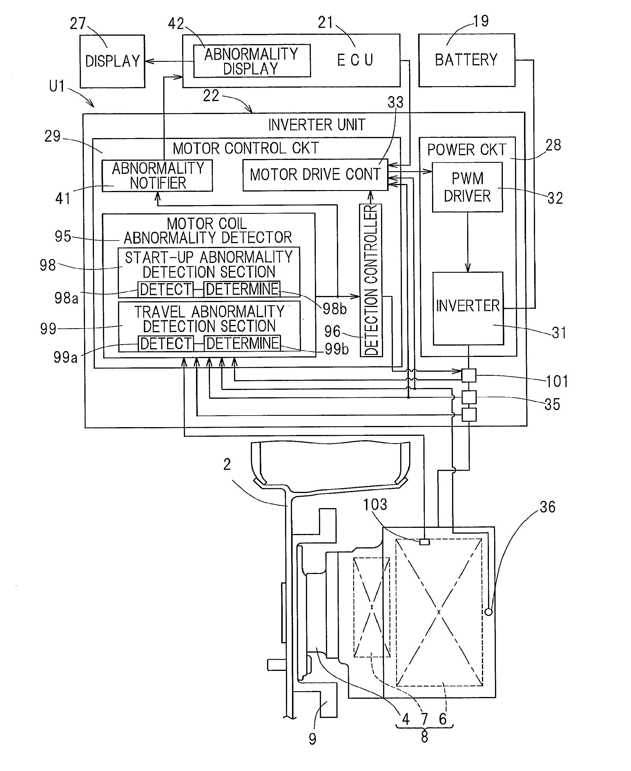
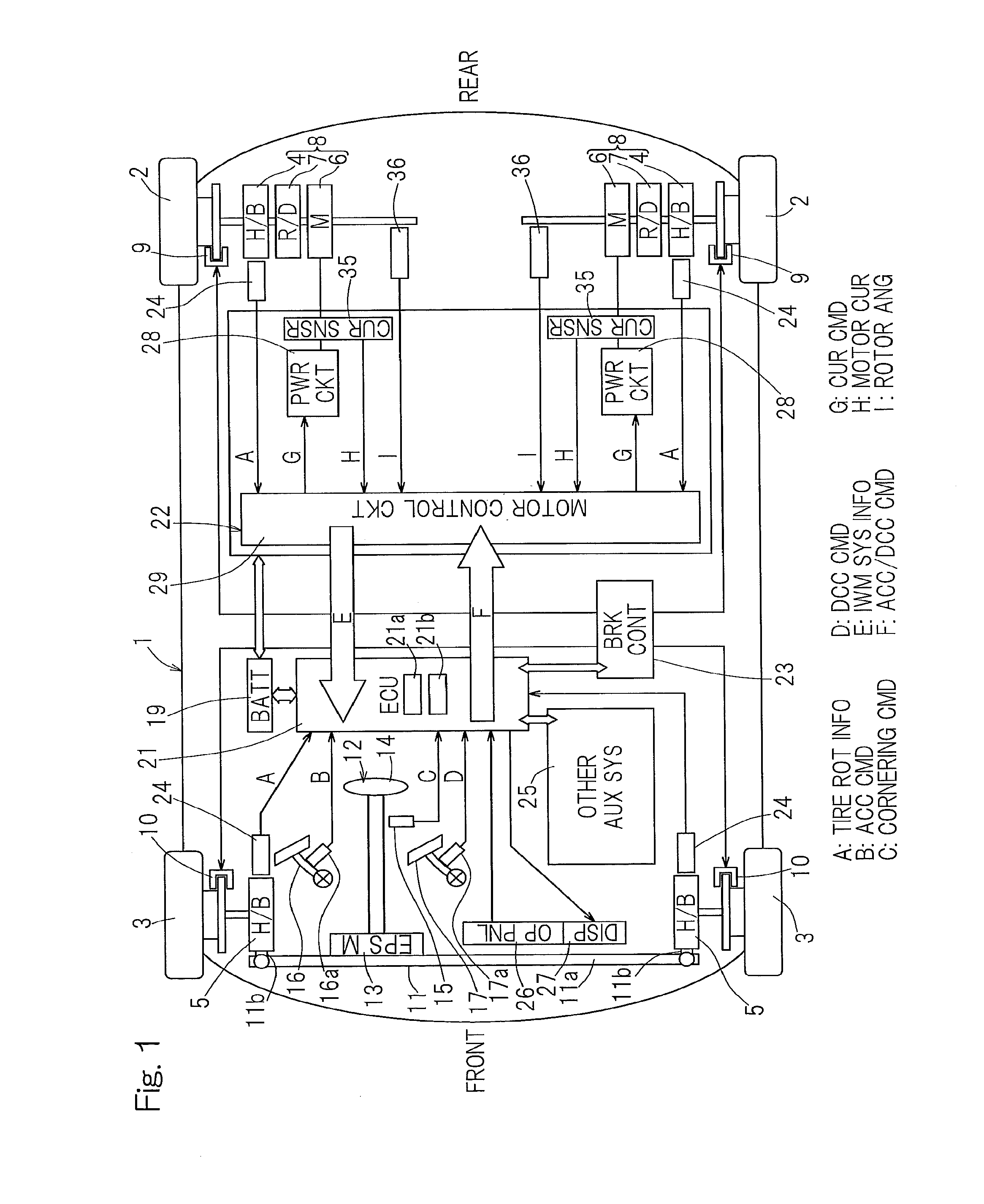
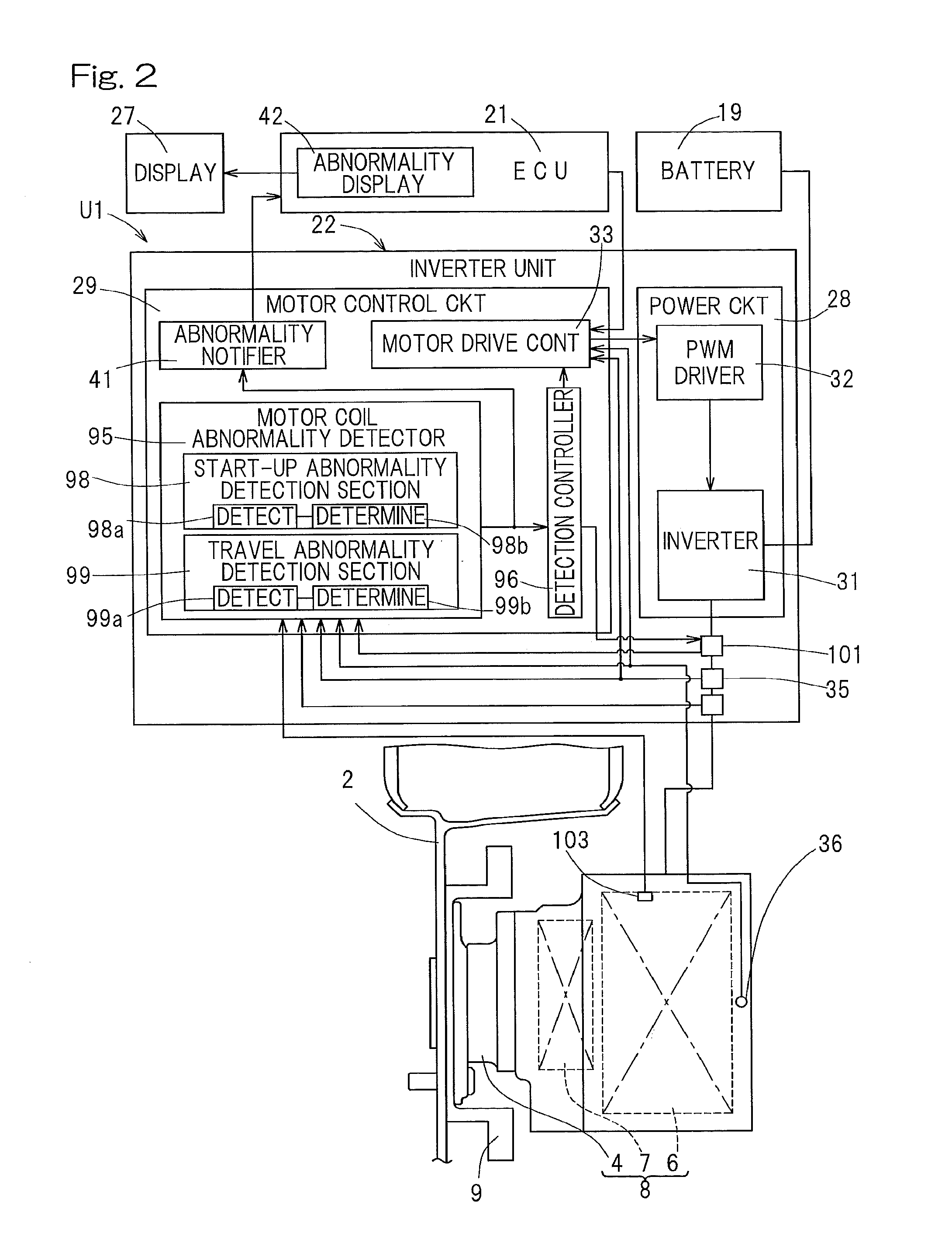
[0036]A diagnostic apparatus for a drive motor and a diagnostic method, both used in an electric vehicle, which are designed in accordance with the present invention will be described with particular reference to FIGS. 1 to 9. The diagnostic apparatus for the drive motor is mounted on the electric vehicle. This electric vehicle is a four wheeled vehicle of a type in which as shown in FIG. 1, wheels 2, which serve as respective rear wheels 2 on left and right sides of a vehicle body 1, are designed to be respective drive wheels and wheels 3, which serve as respective front wheels 3 on the left and right sides of the vehicle body 1, are designed to be respective steering wheels for driven wheels. Each of those wheels 2 and 3, which are designed as the drive and driven wheels, has a tire and supported by the vehicle body 1 through a respective wheel bearing assembly 4, 5. The wheel bearing assembly 4, 5 shown in FIG. 1 is indicated by “H / B” that is an abbreviation denoting a hub bearin...

second embodiment

[0085]In view of the above, in a second embodiment shown in FIG. 10, in order to objectively determine the coil resistance that has been measured during the non-traveling time, the correction block 104 is provided in the start-up abnormality detection section 98. In this case, by means of a series of experiments, the coil resistance at the time the coil temperature is at a reference temperature (suitably determined temperature in the vicinity of normal temperature) and the coil resistance when the coil temperature elevates are determined. From a plurality of coil resistances so determined, a correction coefficient Kt used in the correction block 104 can be calculated. Accordingly, if in dependence on the coil temperature the coil resistance is corrected by multiplying by the correction coefficient Kt, the occurrence of the abnormality in the motor 6 during the non-traveling time can be further accurately detected. It is to be noted that the motor coil abnormality detector 95 may be ...


PUM


Abstract

A diagnostic apparatus for diagnosing a drive motor of a vehicle includes a start-up abnormality detection section to detect coil temperature, coil resistance or insulation resistance of a motor coil during a non-traveling time in which electric power supply is applied and to determine occurrence of abnormality in the motor coil when the coil temperature is greater than a threshold value or the coil resistance or insulation resistance is greater than a threshold value, and a travel abnormality detection section to detect coil temperature, rotation number of the motor, a motor applied voltage and a motor current during traveling of the vehicle and to determine occurrence of abnormality in the motor coil when the coil temperature is greater than a threshold value or the relation between the motor applied voltage and the motor current relative to the rotation number fails to fall within a predetermined range.

Description

CROSS REFERENCE TO THE RELATED APPLICATION[0001]This application is based on and claims Convention priority to Japanese patent application No. 2011-048633, filed Mar. 7, 2011, the entire disclosure of which is herein incorporated by reference as a part of this application.BACKGROUND OF THE INVENTION[0002]1. Field of the Invention[0003]The present invention relates to an apparatus and a method of diagnosing a motor used in driving a wheel of an electric vehicle and also to a self-diagnosing function of a drive motor.[0004]2. Description of Related Art[0005]In an electric vehicle, malfunction occurring in a motor, which is used to drive a vehicle, and / or a controller used to control the motor markedly affects the performance and safety. In particular, where the electric vehicle makes use of an in-wheel motor drive system, as a result of such device being planned to be downsized, a wheel bearing assembly, a reducer and a motor, all of which are parts of components of the in-wheel motor...

Claims


Application Information

Patent Timeline
IPC IPC(8): G01R31/34B60K7/00B60L3/00H02P21/00H02P21/22H02P27/06H02P27/08H02P29/00H02P29/62
CPCB60L3/0061Y02T10/7275B60L15/2072B60L2220/44B60L2240/36B60L2240/425B60L2240/427B60L2240/429B60L2260/28Y02T10/642B60K7/0007B60K17/046B60K2007/0038B60K2007/0092Y02T10/7005B60L3/00G01R31/34B60L15/007B60L15/2036B60L2240/80B60L2250/10B60L2250/16B60L11/1803B60L50/51Y02T10/64Y02T10/70Y02T10/72
Inventor OZAKI, TAKAYOSHI
Owner NTN CORP
Why Eureka
Try Eureka