Method for mounting connection pins in a component carrier, a die tool for mounting connection pins, a component carrier forming a module for an electronic assembly, and such an assembly

Active Publication Date: 2013-12-26
TELEFON AB LM ERICSSON (PUBL)
View PDF8 Cites 0 Cited by
  • Summary
  • Abstract
  • Description
  • Claims
  • Application Information

AI Technical Summary

Benefits of technology

[0007]The object of the present invention

Problems solved by technology

However, this can be a problem, often due to the fact that the anchoring of the pins in the through-hole of the component carrier nearly always involves some sort of deformation of the pin or the through-hole and/or the component carrier.
Also the assembly technique of soldering the pin in a through-hole can result in lack of sufficient co-planarity.
Other reasons for irregularities in the planarity of the component carrier can be irregularities that existed already in the original component

Method used


Image

  • Method for mounting connection pins in a component carrier, a die tool for mounting connection pins, a component carrier forming a module for an electronic assembly, and such an assembly
  • Method for mounting connection pins in a component carrier, a die tool for mounting connection pins, a component carrier forming a module for an electronic assembly, and such an assembly
  • Method for mounting connection pins in a component carrier, a die tool for mounting connection pins, a component carrier forming a module for an electronic assembly, and such an assembly

Examples


Example

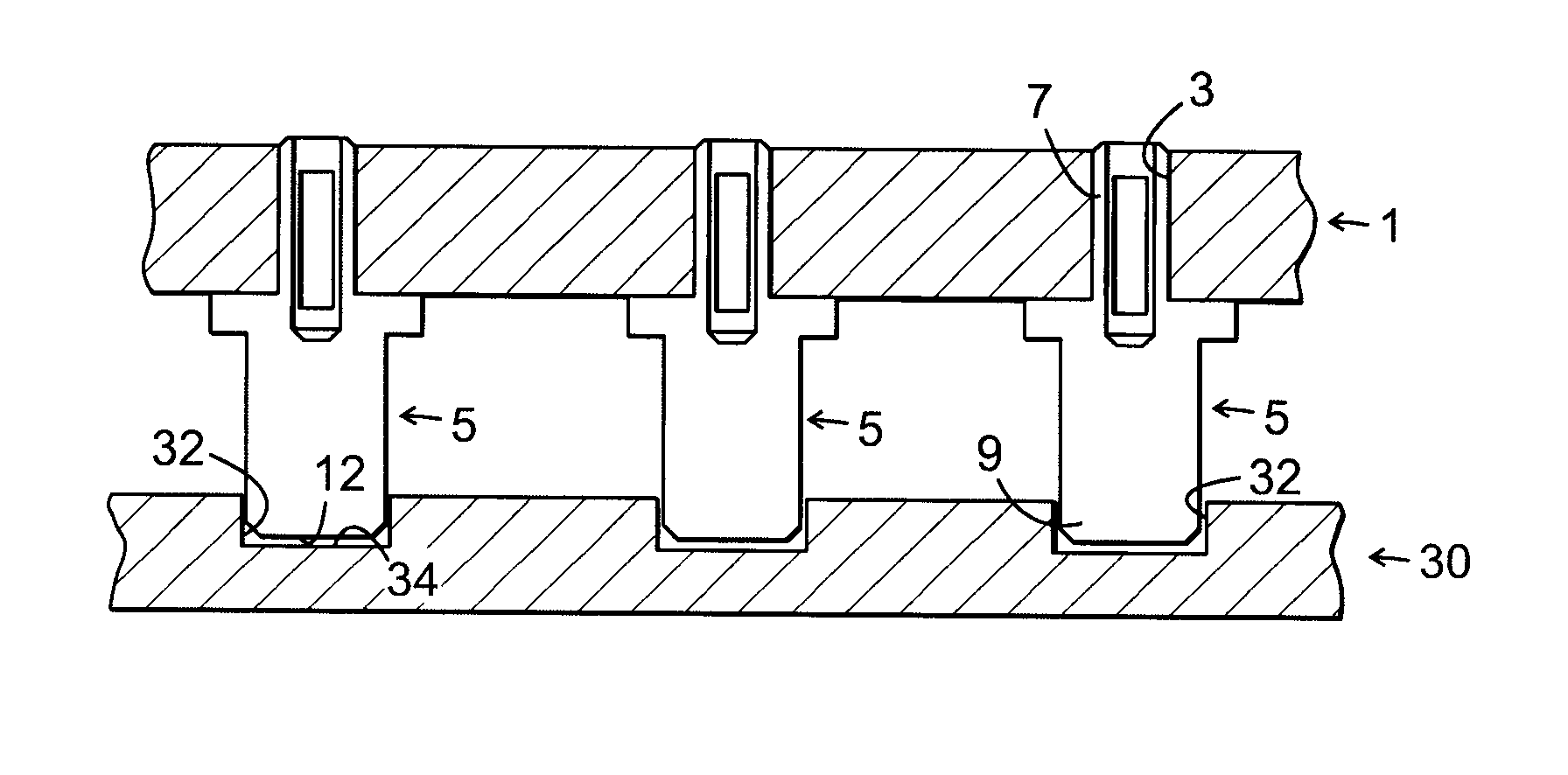
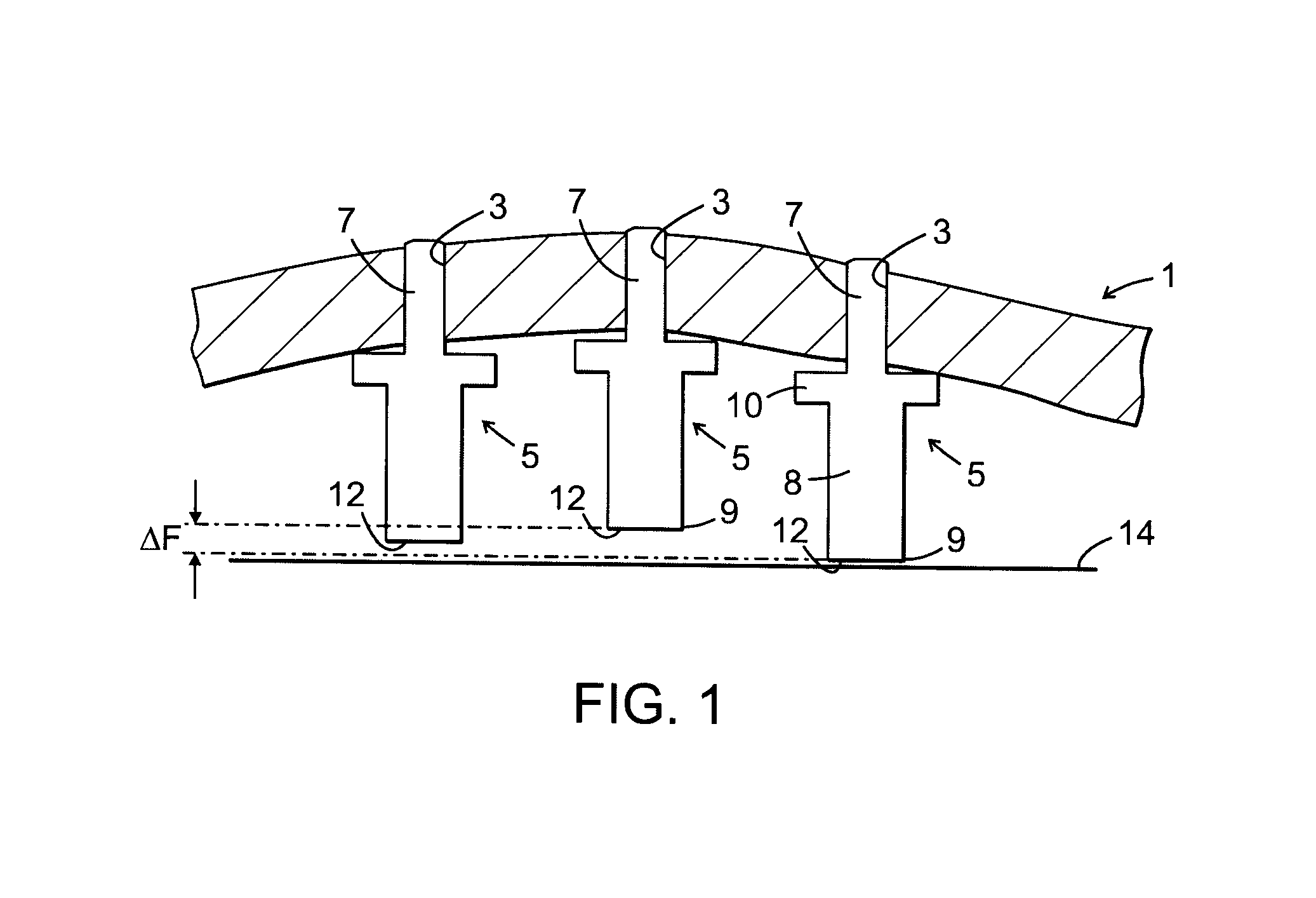
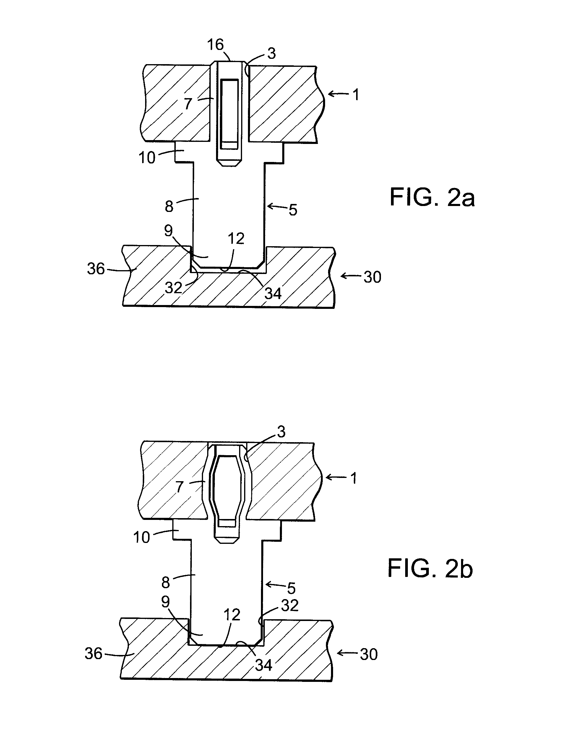
[0034]In FIG. 1 is schematically illustrated a component carrier 1 provided with through-holes 3 for mounting of connection pins 5. The component carrier with its connection pins form a device that is intended to be used as a module in an electronic assembly. Each connection pin has an anchoring part 7, adapted for insertion into and anchoring in said through-hole 3, and a contact part 8, adapted to extend outside said through-hole 3 and having a contact end 9 adapted for contact with the surface of another module of the electronic assembly. The connection pin further includes a flange part 10 adapted to abut against said component carrier and located between said anchoring part 7 and said contact part 8. In the illustrated example, the component carrier 1 is not completely flat or plane, but is slightly curved in relation to a horizontal plane. It should be noted that the curvature in FIG. 1 is grossly exaggerated, for illustrative purposes. The non flatness / planarity of the compon...


PUM

PropertyMeasurementUnit
Lengthaaaaaaaaaa
Lengthaaaaaaaaaa
Lengthaaaaaaaaaa

Abstract

A method for mounting connection pins in respective through-holes. Each pin having an anchoring part for insertion into said through-hole, a contact part to extend outside said through-hole and having a contact end for contact with the surface of another module of the electronic assembly, and a flange part to abut against said component carrier and located between said anchoring part and said contact part. A die tool has several similar recesses all adapted to receive a contact end of the contact part of a connection pin. The anchoring part of the pin is inserted in a through-hole of the component carrier, and the pin is anchored in the component carrier by exerting a force on a free end of the anchoring part of the pin while an end surface of the contact end abuts the bottom surface of similar recesses in the die tool.

Description

TECHNICAL FIELD OF THE INVENTION[0001]The present invention relates to a method for mounting connection pins in respective through-holes provided in a component carrier for an electronic assembly, a die tool for mounting connection pins in the component carrier, and a corresponding component carrier forming a module for an electronic assembly. The invention also relates to an electronic assembly.BACKGROUND OF THE INVENTION[0002]In the electronics industry, connection pins are widely used to provide connection between different parts of an electronic assembly. The connection pins are e.g. mounted in a through-hole in a component carrier or they are surface mounted to a component carrier, which component carrier can have different applications and / or combinations thereof, such as: the component carrier can be part of a printed circuit board, it can carry electronic components and form a component board, it can carry modules such as power modules or stackable modules comprising differe...

Claims


Application Information

Patent Timeline
IPC IPC(8): H05K13/04H05K1/18
CPCH05K13/04H05K13/0447H05K1/181H05K3/301H05K3/325H05K3/3447H05K2201/10303H05K2201/1059H05K2201/10871H05K2203/0195Y10T29/53209Y10T29/49147
Inventor PEREZ-URIA, IGORARVIDSSON, OLA
Owner TELEFON AB LM ERICSSON (PUBL)
Why Eureka
Try Eureka