
Automatic exchange remote transmission system of multipath high definition signals

An automatic exchange and remote transmission technology, applied in the field of signal exchange and transmission, can solve the problems of not supporting IP control function, unable to update control software, inconvenient control and management, etc., to increase IP control function, save power adapter, and meet market demand Effect

Inactive Publication Date: 2014-05-14
HANK ELECTRONICS
View PDF6 Cites 0 Cited by
  • Summary
  • Abstract
  • Description
  • Claims
  • Application Information

AI Technical Summary

Problems solved by technology

The previous product display method used 8 digital tubes to display, only showing the number of current input signal ports; in terms of switching control chips, the traditional one-time programming single-chip microcomputer cannot update the control software, and the single-chip microcomputers with 9 different programs are completely independent , the system is not easy to control and manage, and some bugs cannot be removed, which has certain limitations; in terms of appearance, the traditional product is on the front panel of the IR channel. When the IR line is connected, it is not beautiful (only forward IR is supported), and the panel has 8 An independent circular tangent button, the input and output are LED display; in terms of control mode; the old product uses IRforward control channel, RS232 one-way control, hexadecimal command 600 baud rate; in addition, there are the following defects: 1. CEC BYAPASS Hard switch, default CEC ON when booting; 2. Manual control of the fan; 3. The memory function of the remote control has silk screen, but the actual machine has no memory function; and there is no POE function at all, only 2 Ethernet interfaces, and does not support IP control function

Method used


Image

  • Automatic exchange remote transmission system of multipath high definition signals
  • Automatic exchange remote transmission system of multipath high definition signals
  • Automatic exchange remote transmission system of multipath high definition signals

Examples


Embodiment Construction

[0028] The present invention is realized in this way, the HD BASE-T receiving module, the structural housing and the functional modules connected in the structural housing,

[0029] The HD BASE-T receiving module is located outside the casing;

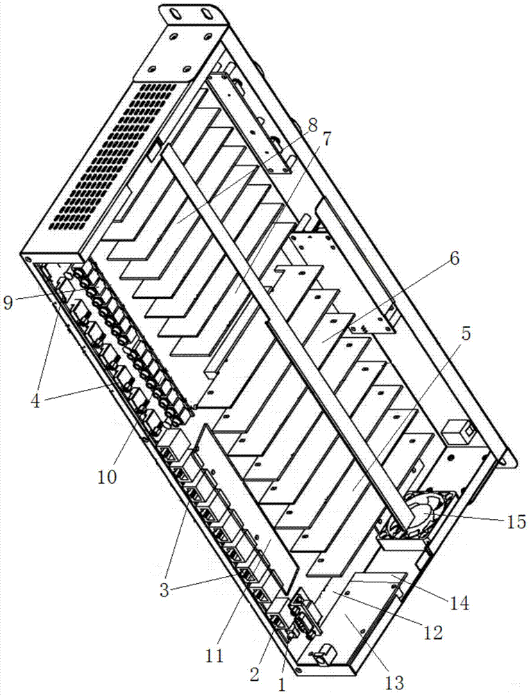
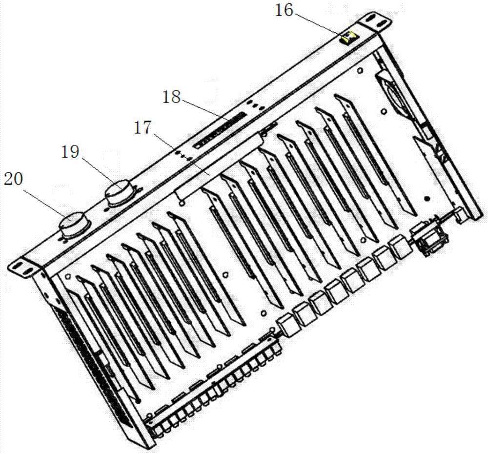
[0030] Such as figure 1 and 2 As shown, the side wall of the structural housing is fixed with a case cooling fan 15, and the side wall of the adjacent structural housing is connected with an LCD display panel 18, and the side wall of the structural housing with the same position as the LCD display panel 18 The outside is also fixedly connected with a signal output port selection knob 19, a signal input port selection knob 20 and a power supply boat switch 16; a reset button 1 is also provided in the structural shell;

[0031]The functional modules include Ethernet port 2, HD BASE-T output port 3, HDMI signal input port 4, module circuit I, module circuit II, EDID management circuit 8, IR transmitting channel interface 9, IR receiving...


PUM


Abstract

The invention discloses an automatic exchange remote transmission system of multipath high definition signals. The automatic exchange remote transmission system comprises a high definition (HD) BASE-T receiving module, a structure casing and a function module connected into the structure casing, wherein the HD BASE-T receiving module is positioned out of the structure casing; the structure casing comprises a case cooling air fan, a liquid crystal display (LCD) display board, a signal output port selection knob, a signal input port selection knob and a power supply ship-shaped switch; a reset key is arranged in the structure casing; the function module comprises an Ethernet port, a HD BASE-T output port, a high-definition multimedia interface (HDMI) signal input port, a module circuit I, a module circuit II, an extended display identification data (EDID) management circuit, an infrared radiation (IR) transmitting channel port, an IR receiving channel port, a packet switching equipment (PSE) board, an RS232 control port, a power supply board, an air fan automatic cooling circuit, a native machine infrared receiving subboard, a mainframe mainboard and a PD board. The automatic exchange remote transmission system integrates audio / video, infrared control and internet protocol (IP) or user datagram protocol (UDP) or transmission control protocol (TCP) control, independent EDID management and functions of an Ethernet switch and power over Ethernet (POE).

Description

technical field [0001] The invention relates to signal exchange and transmission technology, in particular to a multi-channel high-definition signal automatic exchange remote transmission system. Background technique [0002] The old product has no IP control, no independent management of EDID, poor IR compatibility, no POE function, independent management of 9 MCUs, and no mutual communication protocol for each sub-module. RS232 only has one-way control, and there is no return information after the operation is successful. The previous product display method used 8 digital tubes to display, only showing the number of current input signal ports; in terms of switching control chips, the traditional one-time programming single-chip microcomputer cannot update the control software, and the single-chip microcomputers with 9 different programs are completely independent , the system is not easy to control and manage, and some bugs cannot be removed, which has certain limitations...

Claims


Application Information

Patent Timeline
IPC IPC(8): H04N5/222H04N5/268
Inventor 周育春胡海龙
Owner HANK ELECTRONICS
Learn More