
Image encoding apparatus and its control method

Active Publication Date: 2013-12-26
CANON KK
View PDF4 Cites 3 Cited by
  • Summary
  • Abstract
  • Description
  • Claims
  • Application Information

AI Technical Summary

Benefits of technology

The invention provides an image encoding apparatus that determines the size of each encoder block based on its position and the amount of code it generates. It also controls the code amount based on the size of the previous block, resulting in optimal quantization control and better image quality. The apparatus uses predetermined encoding information to restrict the size of the encoder block, resulting in efficient and effective image encoding.

Problems solved by technology

However, since the quantization coefficient can be determined every encoding block size, a code amount error serving as a difference between a target code amount and a generated code amount of each block increases, so that a deterioration in picture quality is caused.

Method used


Image

  • Image encoding apparatus and its control method
  • Image encoding apparatus and its control method
  • Image encoding apparatus and its control method

Examples


first embodiment

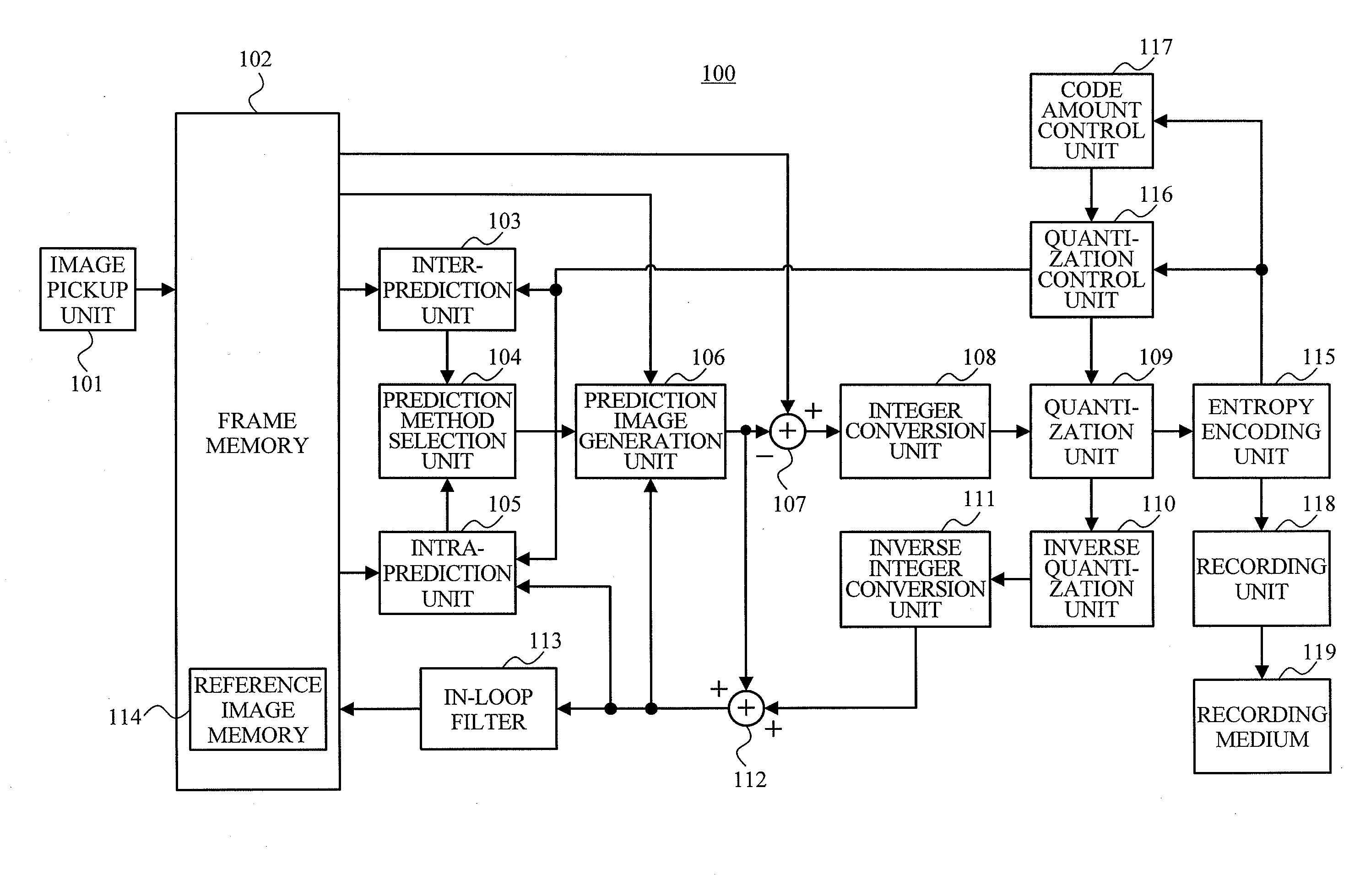
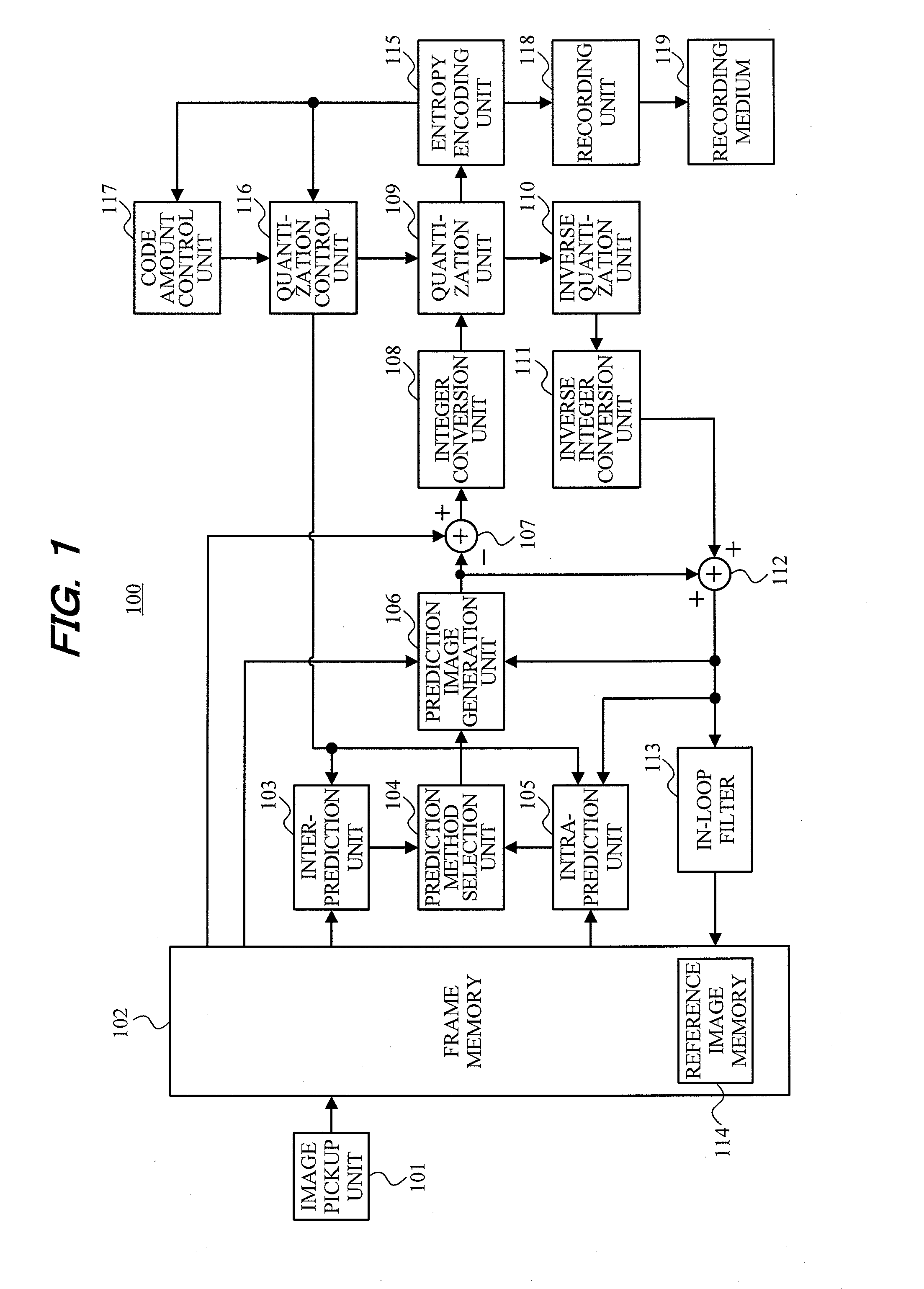
[0021]FIG. 1 is a block diagram illustrating a constructional example of an image encoding apparatus 100 according to the invention.

[0022]In FIG. 1, the image encoding apparatus 100 includes: an image pickup unit 101 including a camera unit such as lenses, image pickup sensor, and the like; and a frame memory 102 for storing moving image data which is output from the image pickup unit. The image encoding apparatus 100 further includes: an inter-prediction unit 103 for searching for a motion vector by a difference between pictures; a prediction method selection unit 104 for selecting a prediction method of either an inter prediction or an intra prediction; and an intra-prediction unit 105 for selecting an intra-prediction method. Further, in order to perform a prediction encoding on an encoding block unit basis by the selected prediction method, the image encoding apparatus 100 includes: a prediction image generation unit 106; a subtractor 107; an integer conversion unit 108; a quant...

second embodiment

[0059]Subsequently, the invention will be described with reference to FIGS. 6 and 7.

[0060]FIG. 6 illustrates a flowchart for the control operation of the quantization control unit 116 according to the present embodiment. In the flowchart, the same processings as those in the first embodiment (FIG. 5) are designated by the same step numbers and their description is omitted here unless otherwise necessary in particular. Since a main construction of the image encoding apparatus of the present embodiment is similar to that of the first embodiment, its description is also omitted here.

[0061]In the control operation of the present embodiment, portions different from those in the first embodiment will be described hereinbelow.

[0062]In a manner similar to the first embodiment, after information necessary for the quantization control is set and arithmetic operations are performed, in step S607, an encoding error rate per picture unit is calculated from the picture encoding rate, the picture ...


PUM


Abstract

An image encoding apparatus for encoding image data including a plurality of frames, determines an encoding block size of an encoding subject frame of the image data based on the obtained image data, encodes the obtained image data on an encoding block unit basis in accordance with the determined encoding block size, controls a code amount of the size-decided encoding block based on encoding information regarding the current size-decided encoding block and the encoding block encoded before the current encoding block, operates predetermined encoding information of the encoding subject frame based on the encoding information, and restricts the encoding block size to be determined, in accordance with the operated predetermined encoding information.

Description

BACKGROUND OF THE INVENTION[0001]1. Field of the Invention[0002]The present invention relates to an image encoding apparatus and, more particularly, to an image encoding apparatus for encoding an image on a divided block unit basis and a control method of such an image encoding apparatus.[0003]2. Description of the Related Art[0004]In the related arts, a digital video camera is well-known as a camera-integrated moving image recording apparatus for compression encoding and recording moving image data which is obtained by photographing an object. In recent years, a recording medium for recording moving image data has been changing from a magnetic tape in the related art to a disk-type medium, a semiconductor memory, or the like having high convenience such as random access performance or the like. As a compression method, an MPEG2 method which is capable of achieving a compression at a high compression rate by using a motion prediction between frames is generally used. Further, in rec...

Claims


Application Information

Patent Timeline
IPC IPC(8): H04N7/32
CPCH04N19/00569H04N19/176H04N19/119H04N19/147H04N19/149H04N19/115H04N19/126H04N19/50
Inventor OISHI, AKIHIRO
Owner CANON KK
Learn More