Heat exchanger for passive residual heat removal system

a heat exchanger and residual heat technology, applied in the direction of nuclear reactors, greenhouse gas reduction, nuclear elements, etc., can solve the problems of inferior cooling efficiency, large-capacity heat exchangers must be manufactured, water may not be periodically supplemented, etc., to achieve the effect of improving heat transfer efficiency, and increasing the heat transfer area

Active Publication Date: 2013-12-26
KOREA ATOMIC ENERGY RES INST
View PDF3 Cites 21 Cited by
  • Summary
  • Abstract
  • Description
  • Claims
  • Application Information

AI Technical Summary

Benefits of technology

[0013]The present invention has been made to solve the problems occurring in the prior art, an object of the present invention is to provide a heat exchanger for a passive residual heat removal system capable of effectively removing the residual heat radiated from the core by taking the characteristics of water-cooled and air-cooled schemes into consideration when the nuclear reactor is stopped due to the accident.
[0021]Further, in the case of entering the air-cooled type cooling step, even if the water is not supplemented into the emergency cooling tank from the outside, the nuclear reactor can be safely maintained through the air-cooled scheme for a long time. Accordingly, the safety of the nuclear reactor can be significantly improved.

Problems solved by technology

In contrast, according to an air-cooled type condensation heat exchanger, the emergency cooling tank is not used, and water may not be periodically supplemented.
However, inferior cooling efficiency is represented, so that a large-capacity heat exchanger must be manufactured.

Method used


Image

  • Heat exchanger for passive residual heat removal system
  • Heat exchanger for passive residual heat removal system
  • Heat exchanger for passive residual heat removal system

Examples


first embodiment

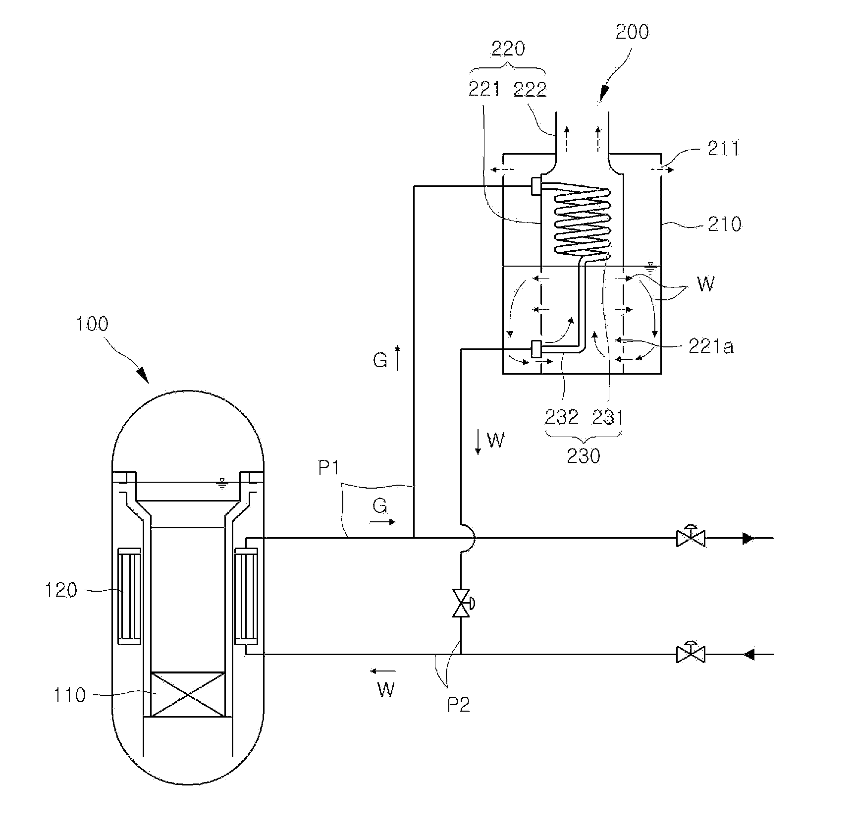
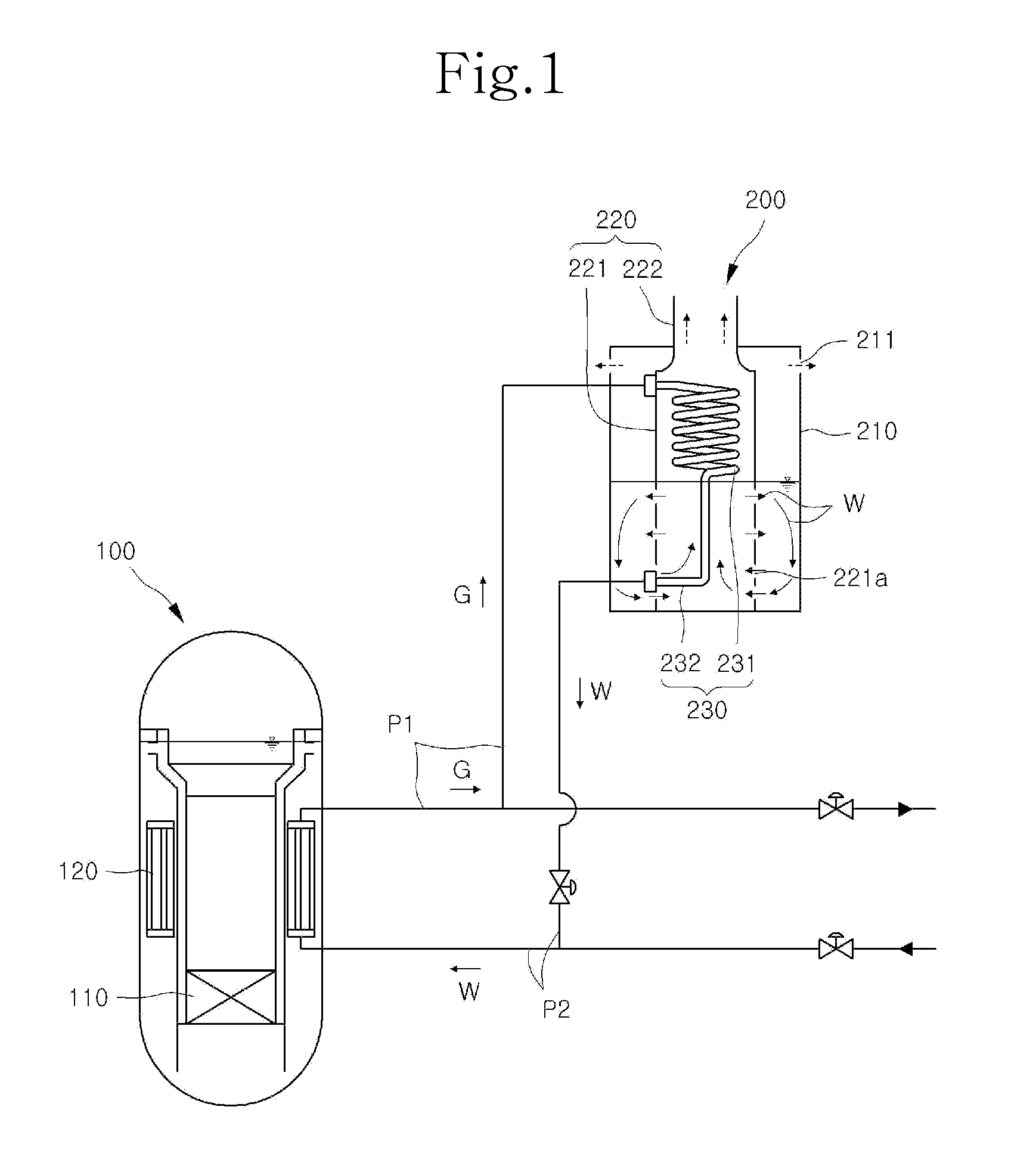
[0030]FIG. 1 is a view showing the structure of a passive residual heat removal system according to the present invention in which the level of water stored in an emergency cooling tank reaches the upper end portion of a straight tube. FIG. 2 is a perspective view showing a heat exchange tube provided in a heat exchanger for the passive residual heat removal system according to the present invention.

[0031]As shown in FIG. 1, a heat exchanger 200 for the passive residual heat removal system according to the present invention is connected to a nuclear reactor 100, and includes an emergency cooling tank 210, a housing 220 inserted into the emergency cooling tank 210, and a heat exchange tube 230 inserted into the emergency cooling tank 210. A plurality of steam circulation holes 211 are provided at an upper lateral side of the emergency cooling tank 210.

[0032]The nuclear reactor 100 includes a core 110 and a steam generator 120 to decrease the temperature of the core 110. The core 110 ...

second embodiment

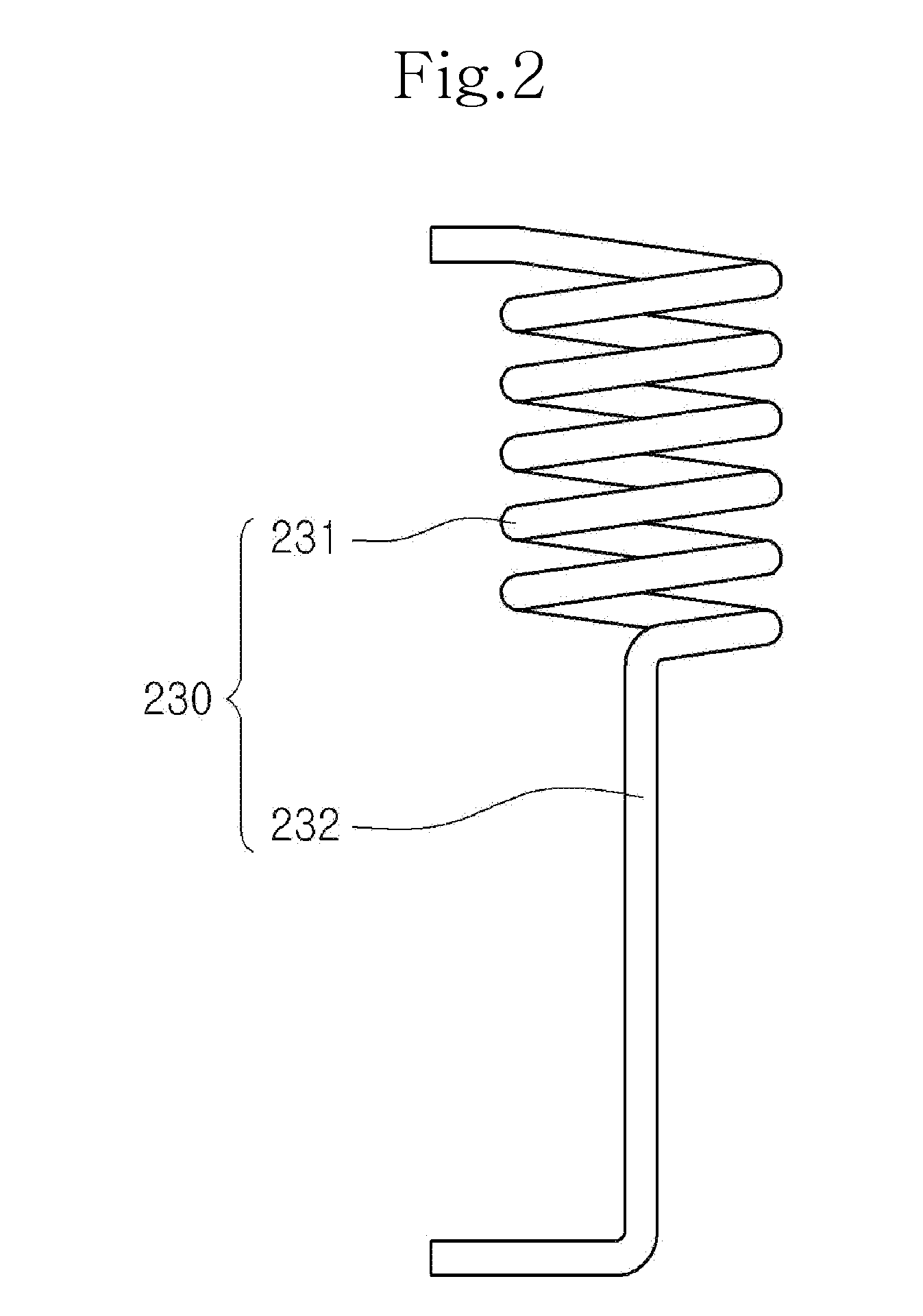
[0060]Hereinafter, the structure of a heat exchange tube 230 according to the present invention will be described with reference to FIG. 3.

[0061]FIG. 3 is a perspective view showing the heat exchange tube 230 provided in a heat exchanger in a passive residual heat removal system according to the second embodiment of the present invention.

[0062]As shown in FIG. 3, the heat exchange tube 230 according to the second embodiment has first and second members having the shape of a spiral tube (including an upper spiral tube and a lower spiral tube). In other words, the first member exposed to the air has the number of spiral turns per length greater than the number of spiral turns per length provided at the second member submerged under the water W, so that the first member is denser than the lower portion of the heat exchanger, thereby expanding the heat transfer area.

[0063]According to the second embodiment, the problem caused in the air-cooled scheme representing the degraded heat trans...

third embodiment

[0064]Hereinafter, the structure of a heat exchange tube 230 according to the present invention will be described with reference to FIG. 4.

[0065]FIG. 4 is a perspective view showing the heat exchange tube 230 provided in a heat exchanger in a passive residual heat removal system according to the third embodiment of the present invention.

[0066]As shown in FIG. 4, the heat exchange tube 230 according to the third embodiment has a first member including a first spiral tube and a second member including a straight tube and a second spiral tube connected to the straight tube. In other words, the heat exchange tube 230 according to the third embodiment includes an upper spiral tube 233 serving as the first spiral tube, a straight tube 232 integrally formed with the upper spiral tube 233, and a lower spiral tube 234 serving as the second spiral tube integrally formed with the straight tube 232.

[0067]One end of the upper spiral tube 233 is connected to the steam pipe P1, one end of the stra...


PUM


Abstract

Disclosed is a heat exchanger for a passive residual heat removal system, which improves heat transfer efficiency by expanding a heat transfer area. A heat exchange tube includes a first member connected to a steam pipe through which steam generated from a steam generator of a nuclear reactor circulates, and a second member connected to both of the first member and a feed water pipe used to supply water to the steam generator provided in the nuclear reactor, and the first member has the shape different from that of the second member, thereby expanding the heat transfer area so that the heat transfer efficiency is improved.

Description

BACKGROUND OF THE INVENTION[0001]1. Field of the Invention[0002]The present invention relates to a heat exchanger for a passive residual heat removal system. In more particular, the present invention relates to a heat exchanger for a passive residual heat removal system, capable of improving heat transfer efficiency by expanding a heat transfer area.[0003]2. Description of the Related Art[0004]Unlike a typical boiler, a nuclear reactor generates residual heat from the core thereof during the significant time periods after the nuclear reactor is stopped due to an accident, and the residual heat generated from the core is rapidly reduced as time elapses after the nuclear reactor is stopped.[0005]A passive residual heat removal system has been employed for various nuclear reactors including an integral nuclear reactor, and used in order to remove the heat (the sensible heat of the nuclear reactor and the latent heat of the core) of the nuclear reactor upon the emergency situation such ...

Claims


Application Information

Patent Timeline
Patent Type & Authority Applications(United States)
IPC IPC(8): G21C15/18
CPCG21C15/18G21C1/326Y02E30/30
Inventor BAE, YOUNG MINKIM, YOUNG INKIM, KEUNG KOOYOO, SEUNG YEOP
Owner KOREA ATOMIC ENERGY RES INST
Why Eureka
Try Eureka