Microphone

a microphone and microphone technology, applied in the field of microphones, can solve the problems of small limit the expansion of the back chamber, and the inability to make the plane area of the microphone, so as to increase the capacity of the back chamber of the acoustic sensor, reduce the plane area

Active Publication Date: 2013-12-26
MMI SEMICON CO LTD
View PDF3 Cites 20 Cited by
  • Summary
  • Abstract
  • Description
  • Claims
  • Application Information

AI Technical Summary

Benefits of technology

[0018]The present invention was made in view of such technical problems as described above, and has an object to provide a microphone capable of reducing a plane area seen from above, and further increasing a capacity of a back chamber of an acoustic sensor.

Problems solved by technology

Especially, it is not possible to make the plane area of the microphone 31 smaller than the sum of a plane area of the acoustic sensor 15 and a plane area of the signal processing circuit 17.
However, even in such a structure, there is a limit on expansion of the capacity of the back chamber 16, and it is small as compared with a capacity of the space inside the package made up of the cover 12 and the circuit board 13.
However, the signal processing circuit is accommodated inside the opening of the tridimensional circuit board, and hence, again, the capacity of the back chamber is small and improving the sensitivity of the microphone is difficult.

Method used


Image

  • Microphone
  • Microphone
  • Microphone

Examples


first embodiment

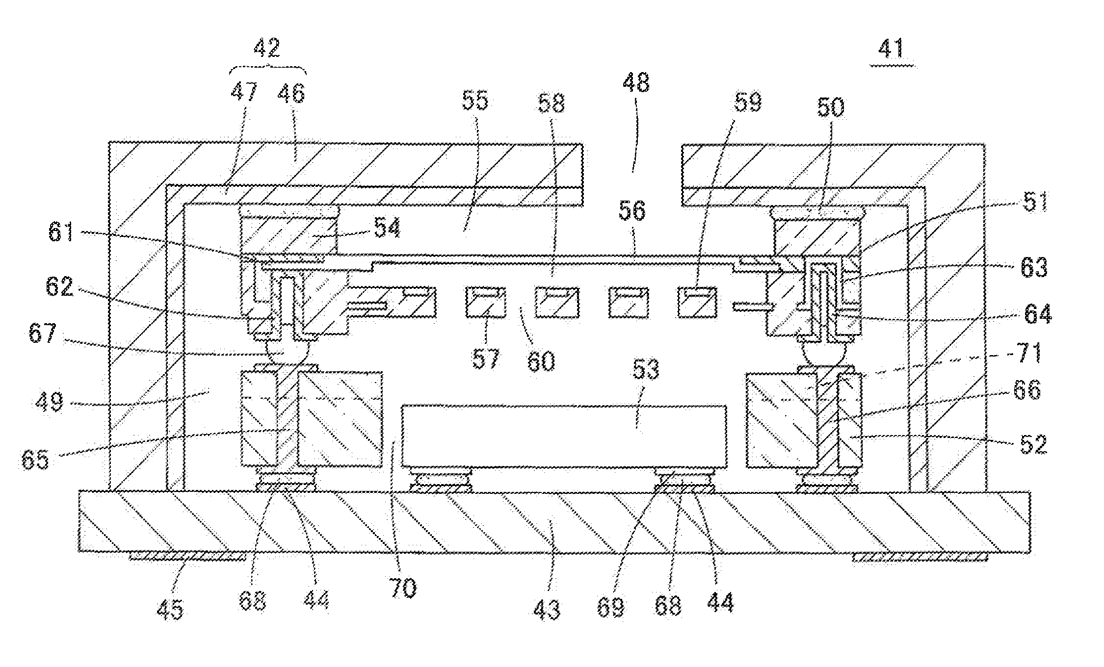
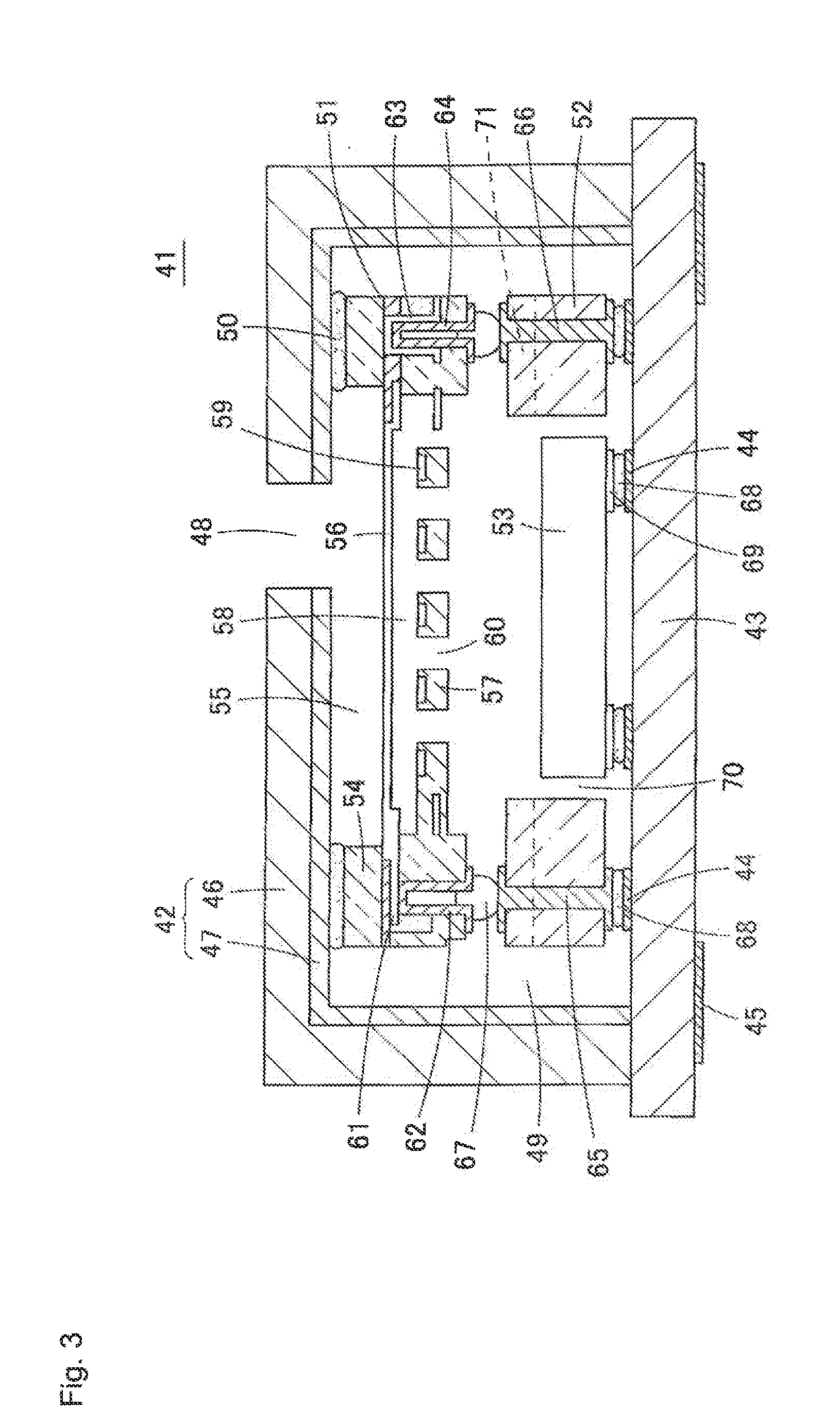
[0043]A microphone according to Embodiment 1 of the present invention will be described with reference to FIGS. 3 to 5. FIG. 3 is a sectional view showing a structure of a microphone 41 according to Embodiment 1. FIG. 4(A) is a perspective view of an interposer 52 (supporting member) used for the microphone 41, and FIG. 4(B) is a perspective view showing a state where the interposer 52 has been vertically inverted. FIGS. 5(A) and 5(B) are sectional views of the interposer 52, and FIG. 5(A) is a cross section taken along line X-X of FIG. 4(A) while FIG. 5(B) is a cross section taken along line Y-Y of FIG. 4(A).

[0044]In the microphone 41, a package is formed of a cover 42 and a circuit board 43. An acoustic sensor 51, the interposer 52 and a signal processing circuit 53 are accommodated inside this package.

[0045]On the top surface of the circuit board 43 constituting part of the package, there are provided a plurality of top-surface electrode pads 44 for joining the interposer 52 and ...

second embodiment

[0075]FIG. 11 is a sectional view showing a microphone 81 according to Embodiment 2 of the present invention. This microphone 81 differs from the microphone 41 of Embodiment 1 only in the shape of the interposer 52. Therefore, descriptions of the microphone 81 of Embodiment 2 will be omitted except for a description of the interposer 52.

[0076]In the interposer 52 used for the microphone 81, the hollow 70 for accommodating the signal processing circuit 53 is formed in box form with the under surface thereof open and the top surface thereof closed, as shown in FIGS. 12(A) and 12(B). On the other hand, ventilation notches 71 in the form of one or a plurality of grooves are provided on the top surface of the interposer 52.

[0077]Therefore, the space (back chamber) below the diaphragm 56 of the acoustic sensor 51 is communicated with the intra-package space 49 through the ventilation notch 71, not via the hollow 70 for accommodating the signal processing circuit 53. This enables the capac...


PUM


Abstract

Provided is a microphone capable of reducing a plane area seen from above, and further increasing a capacity of a back chamber of an acoustic sensor. An interposer 52 is mounted on a top surface of a circuit board 43, and an acoustic sensor 51 is mounted on the top surface thereof. A signal processing circuit 53 is accommodated in a space 70 provided in the interposer 52, and mounted on the circuit board 43. The acoustic sensor 51 is connected to the circuit board 43 through a wiring structure provided in the interposer 52. The acoustic sensor 51, the interposer 52 and the like are covered by a cover 42 put on the top surface of the circuit board 43. In the cover 42, a sound introduction hole 48 is opened in a position opposed to the front chamber of the acoustic sensor 51. The interposer 52 is formed with a ventilation notch 71 for acoustically communicating a space below a diaphragm 56 of the acoustic sensor 51 with a space inside the cover 42 and outside the interposer 52.

Description

TECHNICAL FIELD[0001]The present invention relates to a microphone, and specifically to a microphone with an acoustic sensor mounted inside a package.BACKGROUND ARTGeneral Microphone[0002]FIG. 1 is a sectional view showing a microphone with a conventional general structure. This microphone 11 is obtained by mounting an acoustic sensor 15, a signal processing circuit 17 inside a package made up of a cover 12 and a circuit board 13. The acoustic sensor 15 and the signal processing circuit 17 are mounted in the state of being arranged beside each other on the top surface of the circuit board 13, and the signal processing circuit 17 is covered by a sealing resin 21. The acoustic sensor 15 and the signal processing circuit 17 are electrically connected by a bonding wire 18, and further, the signal processing circuit 17 is connected to intra-substrate wiring 14 of the circuit board 13 by a bonding wire 19.[0003]Normally, the under surface of the circuit board 13 is mounted on a printed wi...

Claims


Application Information

Patent Timeline
Patent Type & Authority Applications(United States)
IPC IPC(8): H04R1/04
CPCH04R1/04H01L2224/16225H04R1/06H04R19/04H01L29/84
Inventor NAKAGAWA, YUSUKEHORIMOTO, YASUHIROINOUE, TADASHITAKAHASHI, TOSHIYUKI
Owner MMI SEMICON CO LTD
Why Eureka
Try Eureka