Polishing apparatus and polishing method

a technology of polishing apparatus and substrate, which is applied in the direction of grinding machine components, manufacturing tools, lapping machines, etc., can solve the problems of increasing the whole polishing time, reducing the throughput, and excessive polishing of the lower film with respect to the target film thickness, so as to improve the accuracy of polishing end point detection

Active Publication Date: 2013-12-26
EBARA CORP
View PDF16 Cites 10 Cited by
  • Summary
  • Abstract
  • Description
  • Claims
  • Application Information

AI Technical Summary

Benefits of technology

[0020]According to the present invention, the polishing end point is detected with use of both the torque current value of the table motor and the optical signal from the optical sensor. Therefore, the polishing end point can be detected before the substrate is polished excessively. Accordingly, it is possible to improve the accuracy of the polishing end point detection.

Problems solved by technology

However, the above-mentioned method of detecting the polishing end point based on the torque current may result in excessive polishing of a wafer if there is a variety in thickness of the upper film over the wafer surface.
Specifically, if the wafer is polished until the lower film is exposed over the wafer surface in its entirety, the lower film may be polished excessively with respect to a target film thickness.
However, this method includes the additional polishing of the wafer, which increases a whole polishing time and lowers a throughput.
However, interconnect patterns formed in the wafer or slurry used in the polishing of the wafer may adversely affect the accuracy of the polishing end point detection, and as a result the required accuracy may not be achieved.

Method used


Image

  • Polishing apparatus and polishing method
  • Polishing apparatus and polishing method
  • Polishing apparatus and polishing method

Examples


Embodiment Construction

[0033]Embodiments of the present invention will be described below with reference to the drawings.

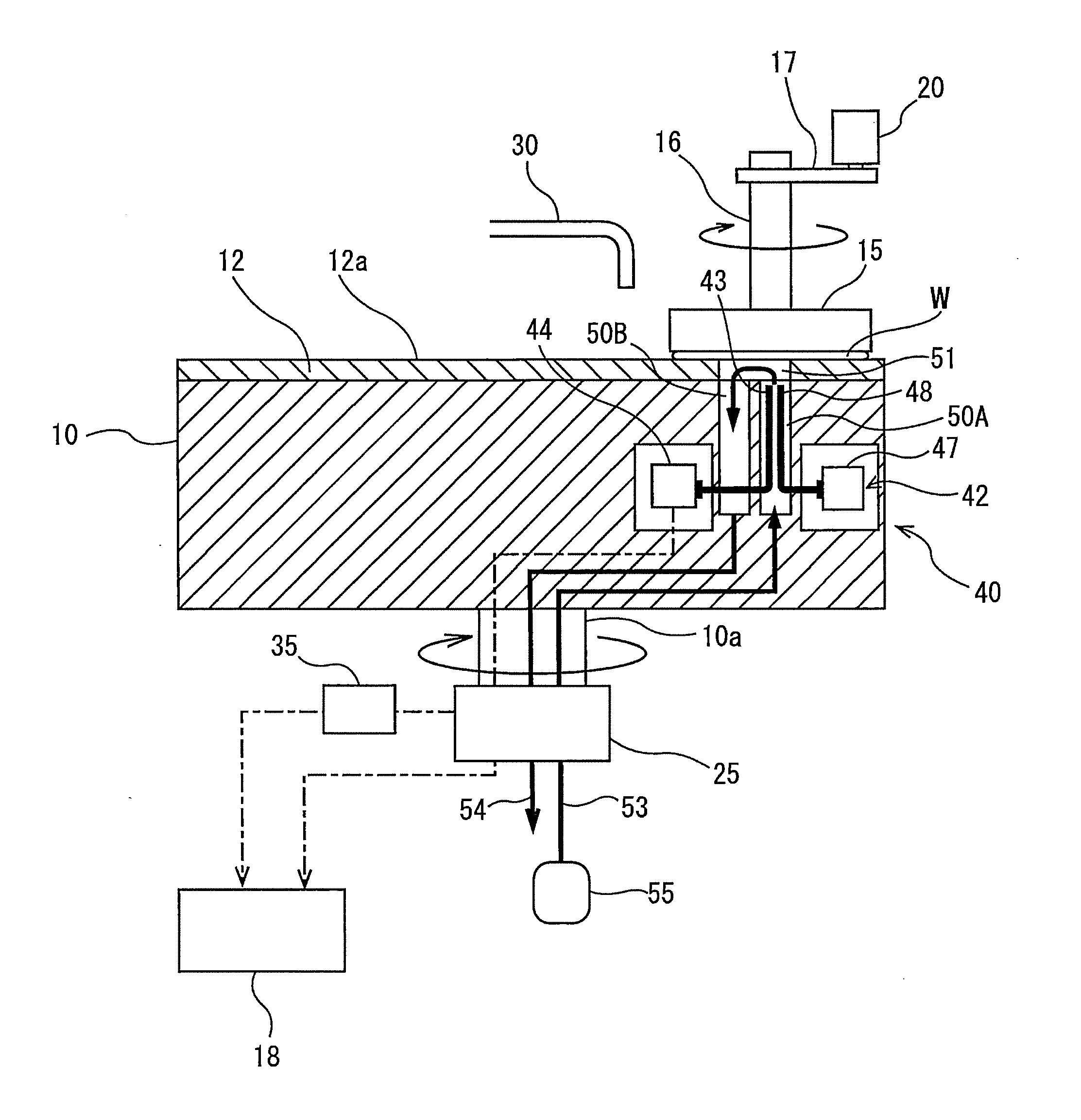
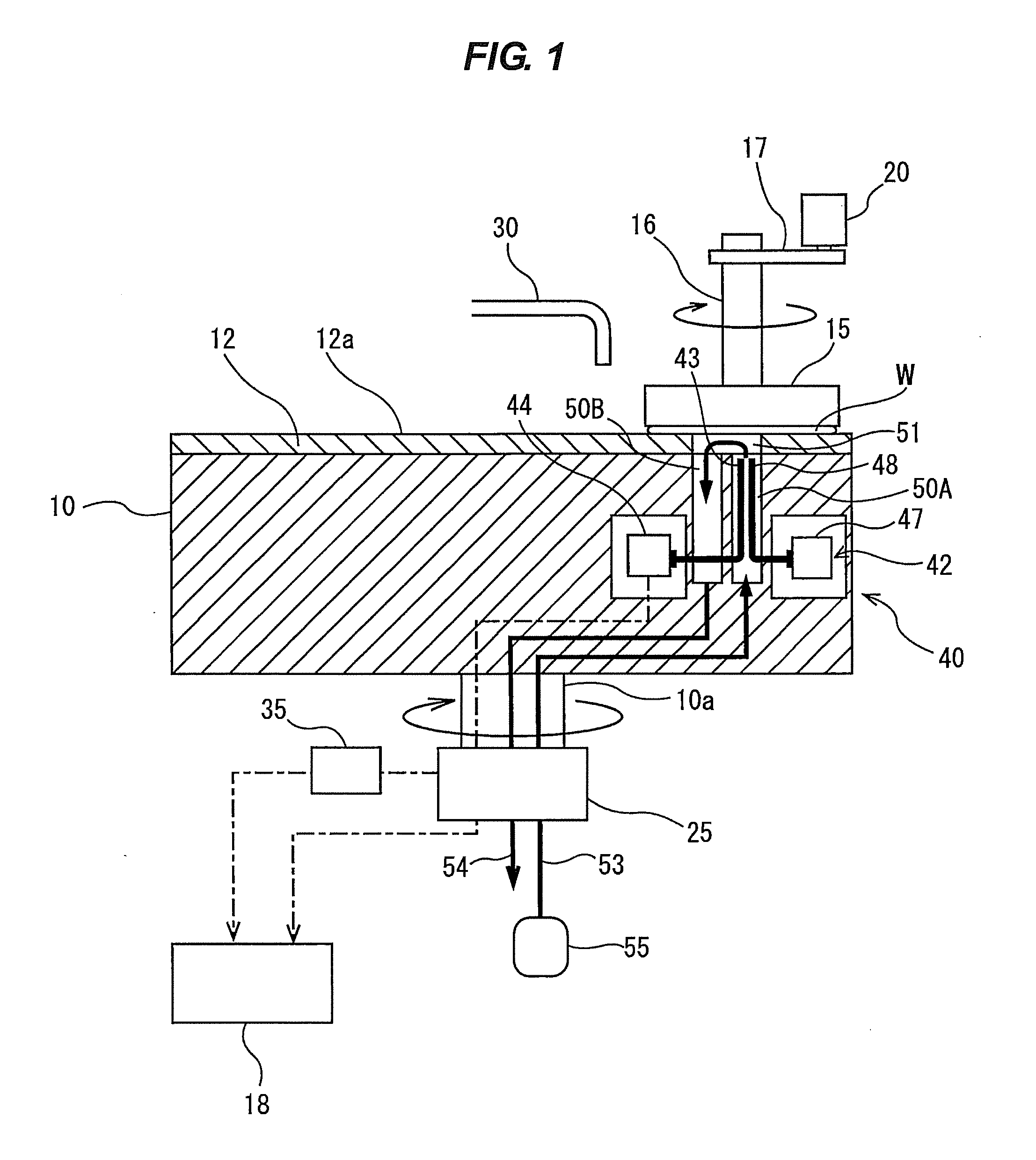
[0034]FIG. 1 is a view of a polishing apparatus according to an embodiment of the present invention. As shown in FIG. 1, the polishing apparatus has a polishing table 10, a top ring 15 supported by a top ring shaft 16, and a processer 18 for detecting a polishing end point of a wafer (substrate) W based on various data. The top ring 15 is configured to hold the wafer W on its lower surface. The top ring shaft 16 is coupled to a top ring motor 20 through a coupling device 17, such as a belt, so that the top ring shaft 16 is rotated by the top ring motor 20. This rotation of the top ring shaft 16 in turn rotates the top ring 15 as indicated by arrow.

[0035]The polishing table 10 is coupled to a table motor 25 through a table shaft 10a, so that the polishing table 10 is rotated by the table motor 25 in a direction as illustrated by arrow. The table motor 25 is located below the polishing ta...


PUM

PropertyMeasurementUnit
thicknessaaaaaaaaaa
thicknessaaaaaaaaaa
thicknessaaaaaaaaaa

Abstract

The present invention provides an apparatus and a method for polishing a substrate having a film formed thereon. The method includes: rotating a polishing table supporting a polishing pad by a table motor; pressing the substrate against the polishing pad by a top ring; obtaining a signal containing a thickness information of the film; producing from the signal a polishing index value that varies in accordance with a thickness of the film; monitoring a torque current value of the table motor and the polishing index value; and determining a polishing end point based on a point of time when the torque current value has reached a predetermined threshold value or a point of time when a predetermined distinctive point of the polishing index value has appeared, whichever comes first.

Description

CROSS REFERENCE TO RELATED APPLICATIONS[0001]This application claims priority to Japanese Patent Application No. 2012-89585 filed Apr. 10, 2012, the entire contents of which are hereby incorporated by reference.BACKGROUND OF THE INVENTION[0002]1. Field of the Invention[0003]The present invention relates to a polishing apparatus and a polishing method for a substrate, such as a wafer, and more particularly to a polishing apparatus and a polishing method capable of detecting a polishing end point of a substrate.[0004]2. Description of the Related Art[0005]Various types of polishing end point detection methods have been used in apparatus for polishing a substrate, such as a wafer. For example, in order to detect a point at which an upper film is removed by polishing of it and as a result a lower film is exposed, a method of detecting a change in a torque current of a polishing table is used (for example, see Japanese laid-open patent publication No. 2001-198813 and Japanese laid-open p...

Claims


Application Information

Patent Timeline
Patent Type & Authority Applications(United States)
IPC IPC(8): B24B37/013
CPCB24B37/013B24B1/002B24B49/10B24B49/12B24B49/16H01L21/304
Inventor HIROO, YASUMASAKOBAYASHI, YOICHIONO, KATSUTOSHI
Owner EBARA CORP
Why Eureka
Try Eureka