Ultrasonic device for cutting and coagulating

a technology of ultrasonic devices and cutting and coagulation, which is applied in the field of ultrasonic surgical systems, can solve problems such as fatigue of surgeon legs, foot pedal getting, and loss of surgical focus

Inactive Publication Date: 2013-12-26
CILAG GMBH INT
View PDF3 Cites 25 Cited by
  • Summary
  • Abstract
  • Description
  • Claims
  • Application Information

AI Technical Summary

Problems solved by technology

A challenge for a forceps-type instrument is how to pivot a clamp pad against the blade.
Key drawbacks with this type of instrument activation include the loss of focus on the surgical field while the surgeon searches for the foot pedal, the foot pedal getting in the way of the surgeon's movement during a procedure and surgeon leg fatigue during long cases.
This approach is limited since the relative motion between the two arms is completely rotational.
This feature limits the ability to control the pressure profile between the two working ends when fully closed.
Further, current designs do not allow for the user to vary the pressure profile at the working end of the instrument.
Some current designs of clamp coagulator shears are not specifically designed for delicate procedures where precise dissection, cutting and coagulation are required to avoid critical blood vessels and nerve bundles.

Method used


Image

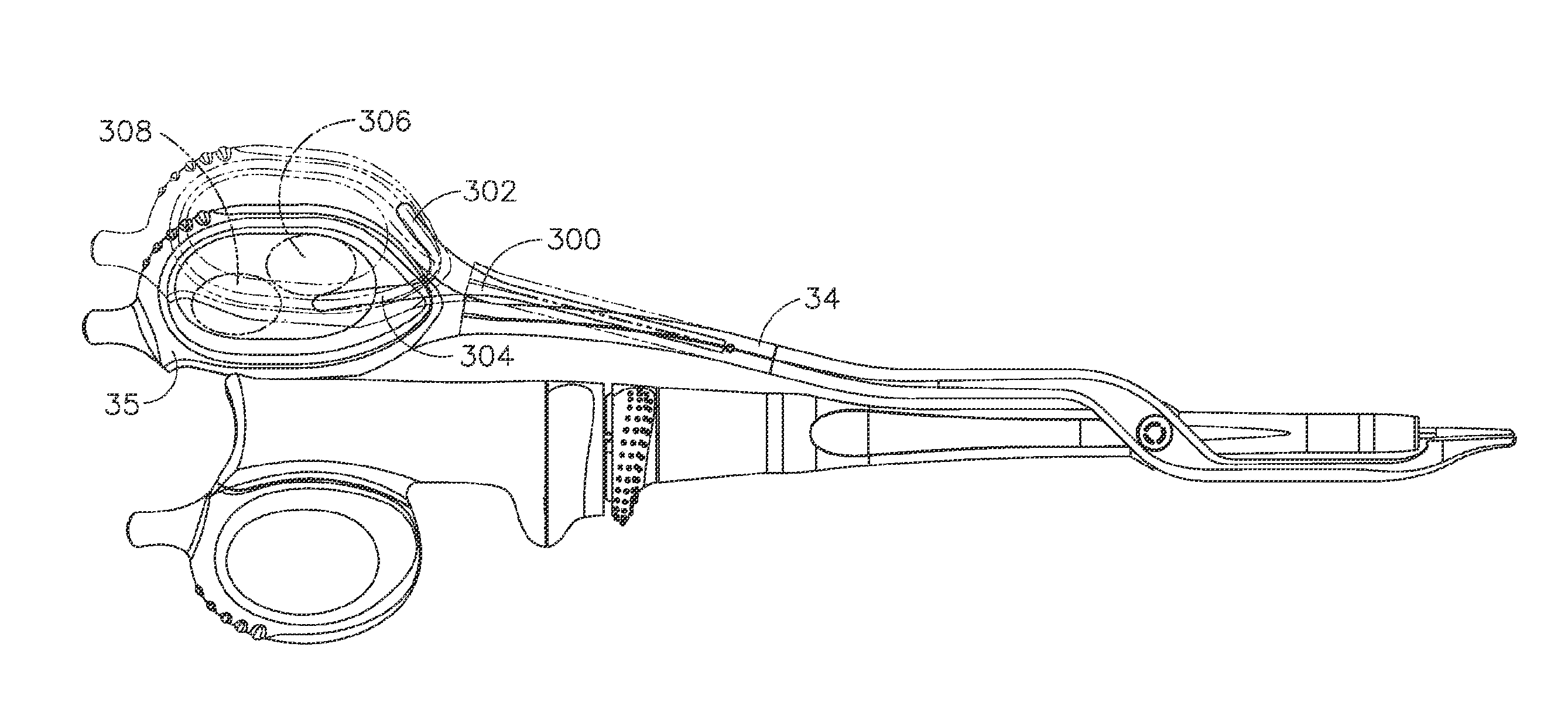
  • Ultrasonic device for cutting and coagulating
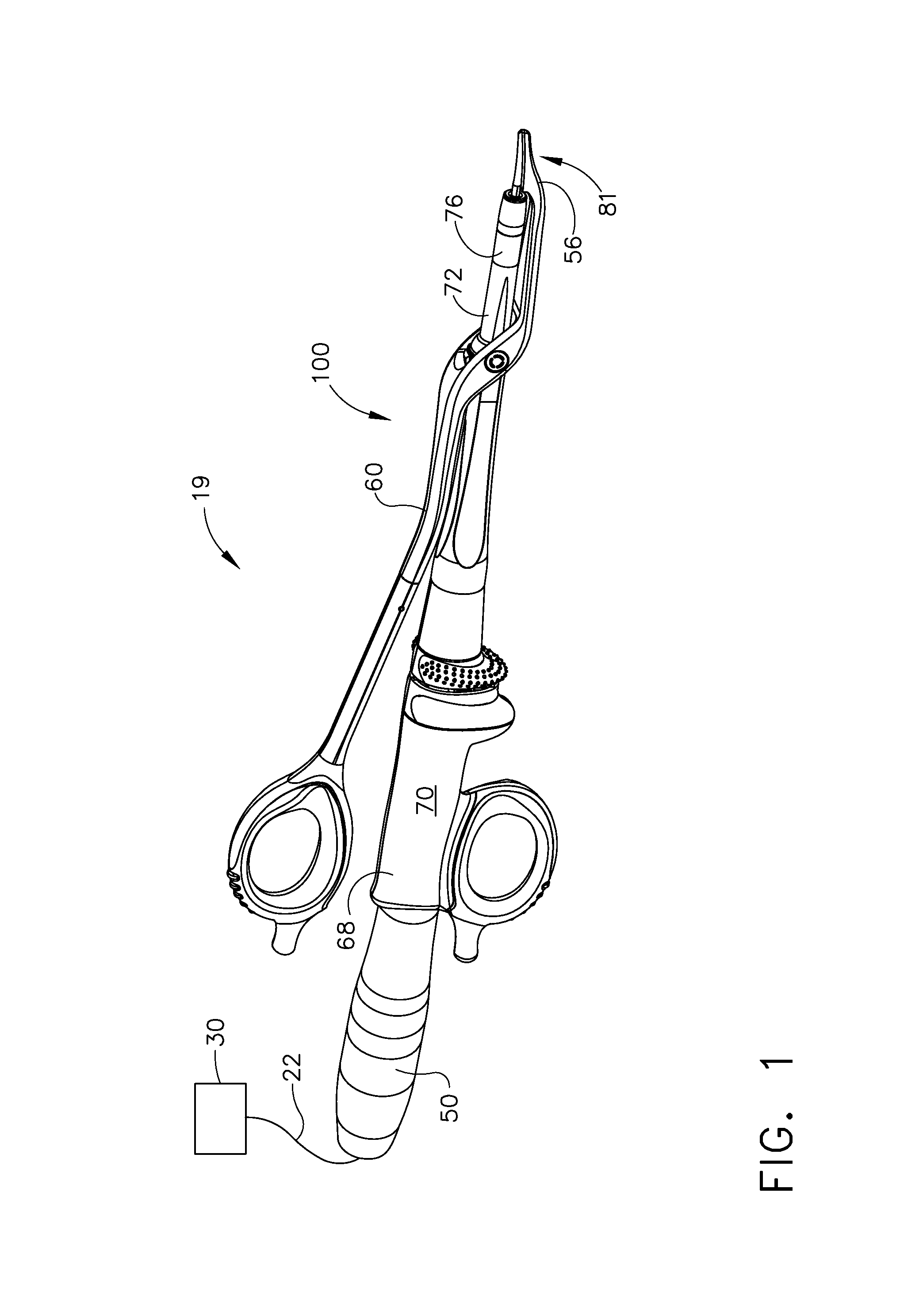
  • Ultrasonic device for cutting and coagulating
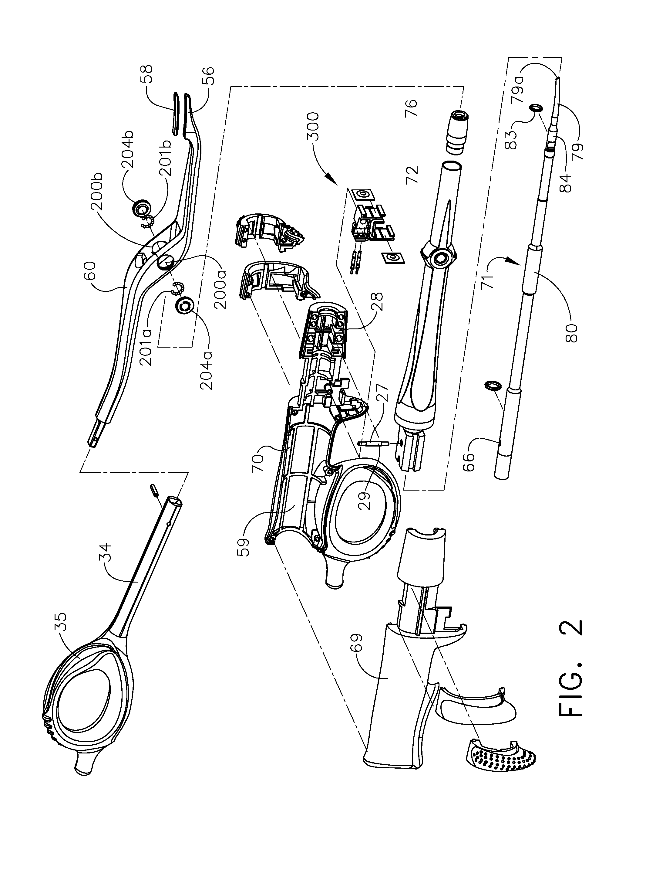
  • Ultrasonic device for cutting and coagulating

Examples


Embodiment Construction

[0035]Before explaining the present invention in detail, it should be noted that the invention is not limited in its application or use to the details of construction and arrangement of parts illustrated in the accompanying drawings and description. The illustrative embodiments of the invention may be implemented or incorporated in other embodiments, variations and modifications, and may be practiced or carried out in various ways. Further, unless otherwise indicated, the terms and expressions employed herein have been chosen for the purpose of describing the illustrative embodiments of the present invention for the convenience of the reader and are not for the purpose of limiting the invention.

[0036]Further, it is understood that any one or more of the following-described embodiments, expressions of embodiments, examples, etc. can be combined with any one or more of the other following-described embodiments, expressions of embodiments, examples, etc.

[0037]The present invention is p...


PUM


Abstract

An ultrasonic clamp coagulator assembly that is configured to permit selective cutting, coagulation, and fine dissection required in fine and delicate surgical procedures. The assembly includes a clamping mechanism, which is specifically configured to provide for variable tissue clamping forces.

Description

REFERENCE TO RELATED APPLICATIONS[0001]The present application is a divisional of U.S. patent application Ser. No. 12 / 823,231, filed on Jun. 25, 2010, abandoned, which claims the priority benefit of U.S. provisional patent application Ser. No. 61 / 221,600, filed on Jun. 30, 2009.FIELD OF THE INVENTION[0002]The present invention generally relates to ultrasonic surgical systems and, more particularly, to an ultrasonic device that is optimized to allow surgeons to perform cutting, coagulation, and fine dissection required in fine and delicate surgical procedures such as an auxiliary node dissection or procedures deep within the internal body cavity.BACKGROUND OF THE INVENTION[0003]Ultrasonic surgical instruments are finding increasingly widespread applications in surgical procedures by virtue of the unique performance characteristics of such instruments. Depending upon specific instrument configurations and operational parameters, ultrasonic surgical instruments can provide substantiall...

Claims


Application Information

Patent Timeline
Patent Type & Authority Applications(United States)
IPC IPC(8): A61B17/32
CPCA61B17/320092A61B2017/00477A61B2017/447A61B17/2804A61B17/2816A61B2017/00469A61B2017/2936A61B2017/320095A61B2017/320094A61B2017/320093
Inventor DANNAHER, WILLIAM D.BERTKE, BRIAN D.MORAN, KENNETHZINGMAN, ARON O.REED, MATTHEW L.PUMMILL, JR., LARRY A.WEAVER, ROBERT D.FRAZIER, JOHN S.
Owner CILAG GMBH INT
Why Eureka
Try Eureka