Dissection handpiece and method for reducing the appearance of cellulite
a cellulite and handpiece technology, applied in the field of surgery tools and implantable devices, can solve the problems of affecting the appearance of cellulite, and causing the appearance of lumps, etc., and achieve the effect of increasing the kinetic energy of fluid
- Summary
- Abstract
- Description
- Claims
- Application Information
AI Technical Summary
Benefits of technology
Problems solved by technology
Method used
Image
Examples
third embodiment
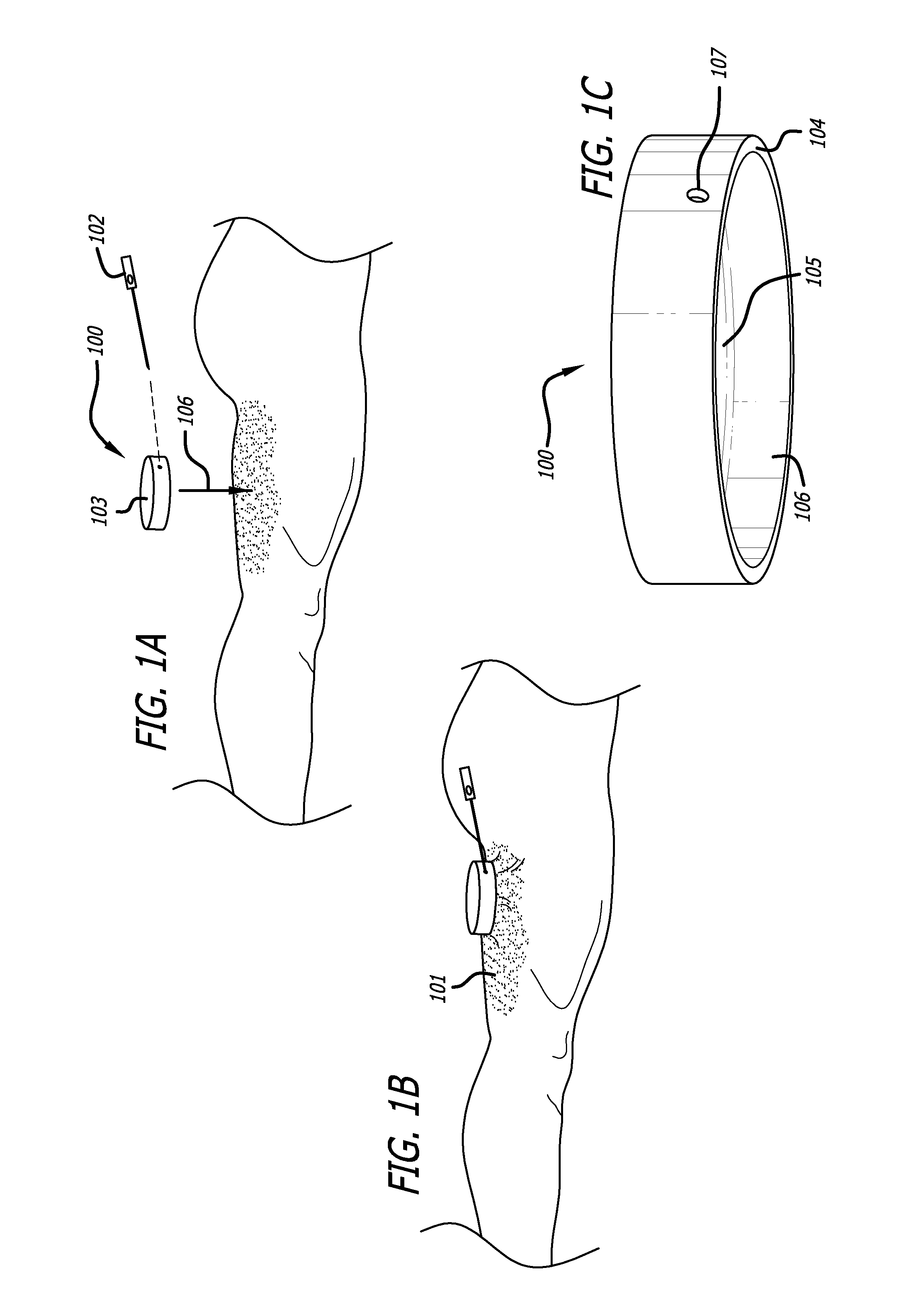
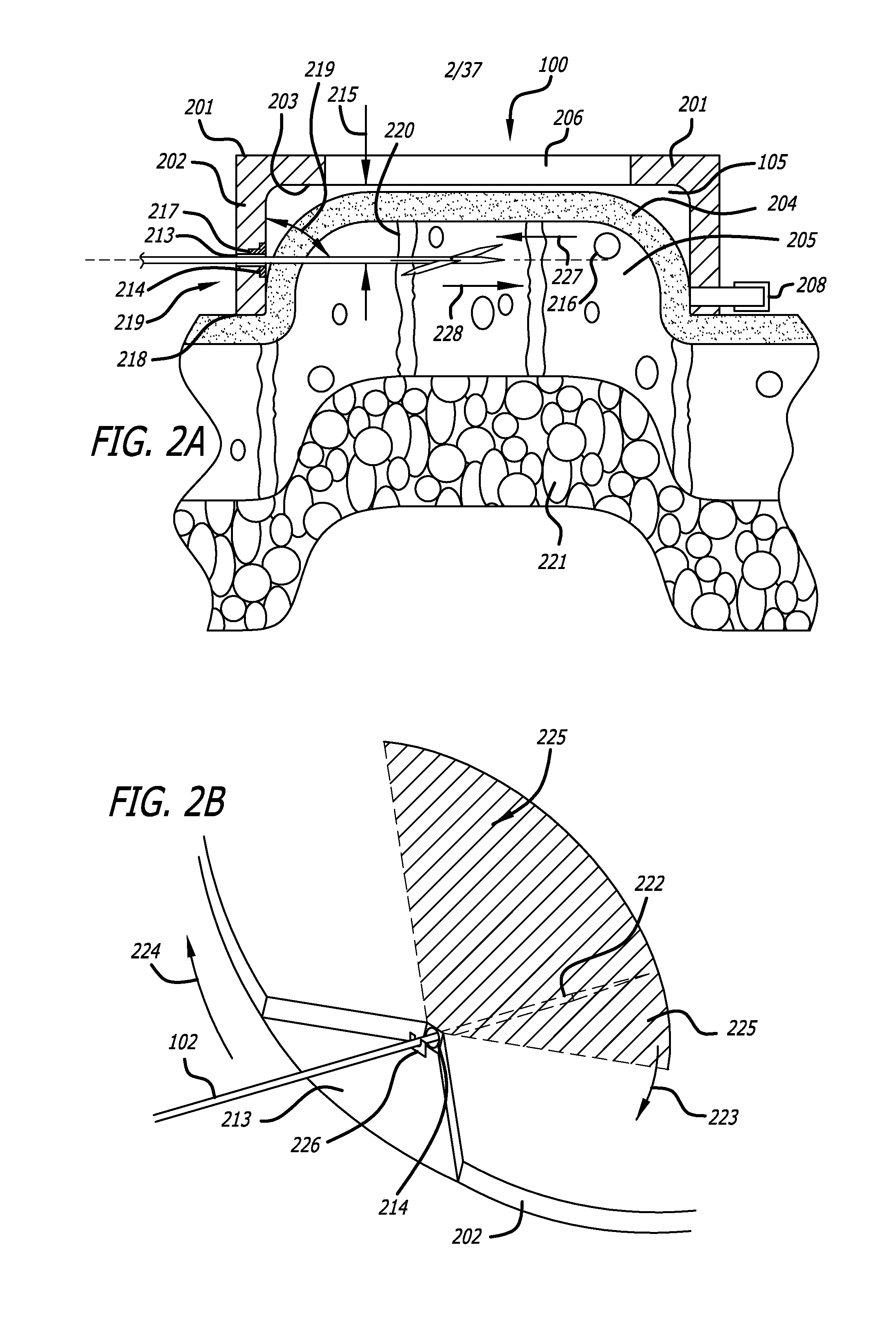
[0108]FIGS. 11A through 11D depict a yet further embodiment of the platform. In this embodiment, platform 309 of the previous embodiments is replaced by support arm 1101 movably coupled to handpiece 100. Support arm 1101 includes a guide pin 1102 which interacts with a guidance track 1103 defined in the top portion of the handpiece 100. A handle 1104 is used to advance support arm 1101 as guided by the interaction of the guide pin 1102 and guidance track 1103. Guide pin 1102 moves within and along guidance track 1103 to stabilize a cutter module 1105 at a proper position proximate to handpiece 100. Cutter module 1105 can be adapted to use any cutting mechanism disclosed herein. In one aspect cutter module 1105 may include cutting implement 102. In another aspect cutting module 1105 is manually controlled. In the depicted embodiment cutting module 1105 is motor controlled and includes a housing, a gear motor, cutting blade 1106, and sleeve 1107 similar to the embodiment depicted by F...
first embodiment
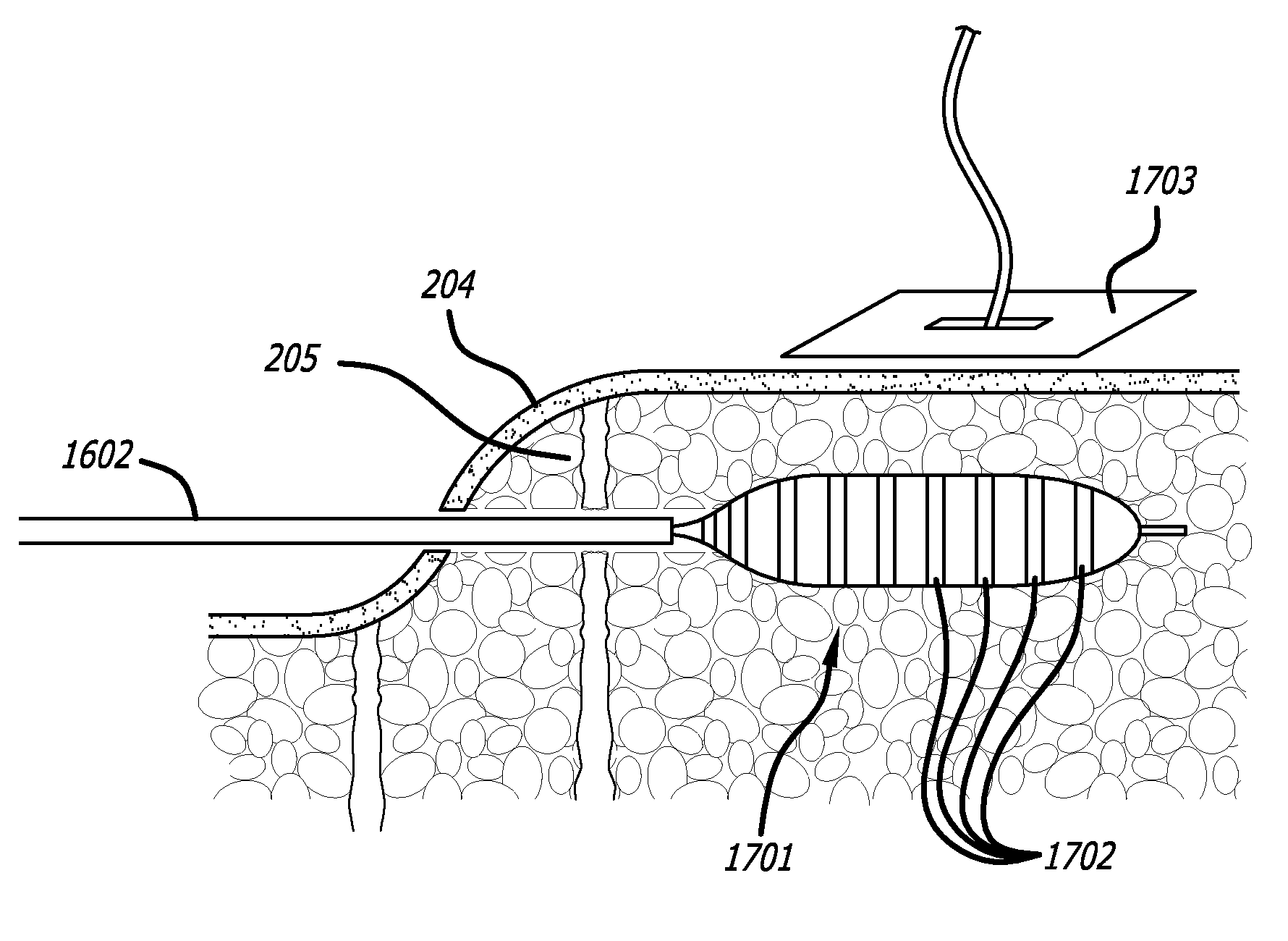
[0175]As shown by FIGS. 23A through 23E, the system may include a mesh deployment applicator 2301 to deploy a fibrous mesh 2302 through a single needle hole in a dermis to create a highly fibrous layer directly or through wound healing processes. The implantable mesh may be self-expandable, and is generally flat, flexible, and can recover its shape and most of its size after compression. In other embodiments mesh 2302 may be detachably coupled to a resiliently compressible self-expandable frame (not illustrated). In a first embodiment, implantable mesh 2302 is preferably disposed at or near a distal end 2303 of deployment applicator 2301. The applicator is inserted percutaneously through the skin using a subdermal catheter such as that described above, or by itself through a hole in the skin, to deploy the implantable mesh located at or near its distal end to a treatment area in the subdermal fat or in the layer between the subdermal fat and the skin. It should be noted that the mes...
second embodiment
[0183]FIGS. 24A through 24F depict a mesh deployment applicator. In this embodiment, a sheath 2305 may include or be interchangeable with an introducer needle 2401, and a guide wire may be omitted. A deployment shaft 2402 and keeper rod 2403 are disposed inside introducer needle 2401. Mesh 2404 is configured to be furled (i.e., rolled up) around shaft 2402 and keeper rod 2403. Introducer needle 2401 (with mesh inside) may then be inserted through an entry wound 2405 created by tool 102. After insertion, needle 2401 slides off over a proximal end 2406 of shaft 2402 and keeper rod 2403, leaving the furled mesh 2404 positioned with subcision region 2407. Shaft 2402 is simultaneously rotated about its longitudinal axis 2408 to un-furl mesh 2404, and pivoted about the skin-entry point 2405 to pull mesh 2404 across subcision region 2407. Keeper rod 2403 is maintained in a fixed position as mesh 2404 is un-furled, so as to anchor the edge of mesh 2404 at the desired location within subcisi...
PUM
 Abstract
Description
Claims
Application Information
 - R&D
- Intellectual Property
- Life Sciences
- Materials
- Tech Scout
- Unparalleled Data Quality
- Higher Quality Content
- 60% Fewer Hallucinations
Browse by: Latest US Patents, China's latest patents, Technical Efficacy Thesaurus, Application Domain, Technology Topic, Popular Technical Reports.
© 2025 PatSnap. All rights reserved.Legal|Privacy policy|Modern Slavery Act Transparency Statement|Sitemap|About US| Contact US: help@patsnap.com


