
Method for quickly connecting a steam generator

a technology of steam generator and steam generator, which is applied in the direction of steam engine plants, machines/engines, mechanical equipment, etc., can solve the problems of steam generator system problems, drum level changes, power plant output cannot be increased as quickly as desired, etc., to achieve short connection time, increase cost effectiveness and the average level of efficiency of the plant, and naturally shorten the start-up time of the power plant

Active Publication Date: 2014-01-02
SIEMENS ENERGY GLOBAL GMBH & CO KG
View PDF6 Cites 7 Cited by
  • Summary
  • Abstract
  • Description
  • Claims
  • Application Information

AI Technical Summary

Benefits of technology

The invention allows for the efficient coupling of steam systems in a power plant, even during start-up of additional steam generators. This is achieved by opening shut-off valves in the steam systems and allowing steam to flow into the further steam generator without stopping the increase in load. The increased output of the second steam generator means that steam temperatures and pressure increase further, and a modified pressure regulation allows for a moderate increase in pressure in the first steam generator while avoiding a split load in the two steam generators. The invention also reduces the complexity of the regulation and simplifies the start-up process of the power plant, resulting in higher efficiency and lower emissions.

Problems solved by technology

If this is not the case variations in pressure, temperature and / or quantity of steam can result in problems within the steam generator systems (drum level changes) or the operation of the steam turbine (limit values being reached, steam turbine trip).
This means that a specific time is needed for this synchronization and the power plant output cannot be increased as quickly as desired.
In addition the steam generated during the connection process is discarded via the bypass station into the condenser and the efficiency of the plant reduced thereby.
In the same way after these steps the low-pressure steam system is also connected to the second steam generator, the disadvantage of this method is that it is very time-consuming.
This method, although faster, conceals the additional risk however of problems developing in a number of systems of the same time and possibly influencing each other.
This method makes an unwanted shutdown of the steam turbine or of the steam generator significantly more likely because limit values have been exceeded (drum level high or low, too little or too much steam in the steam turbine direction).

Method used


Image

  • Method for quickly connecting a steam generator
  • Method for quickly connecting a steam generator
  • Method for quickly connecting a steam generator

Examples


Embodiment Construction

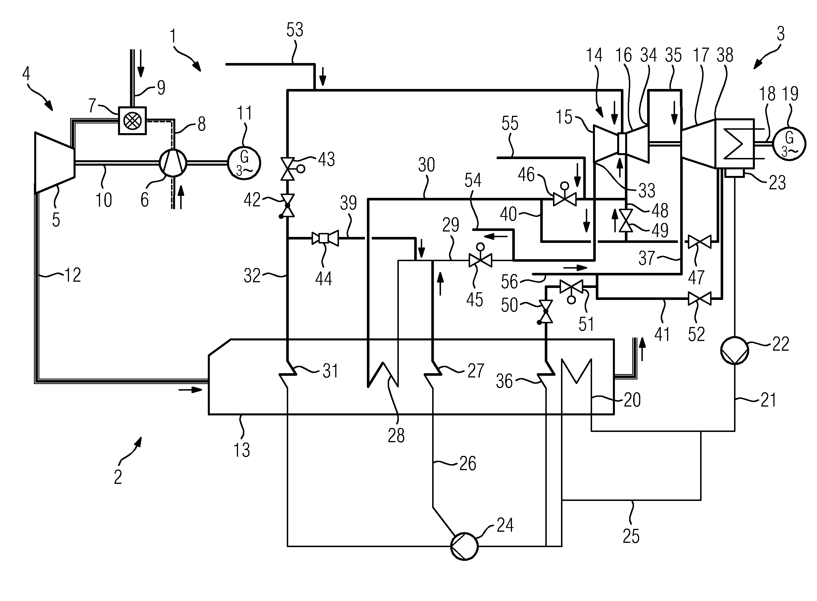
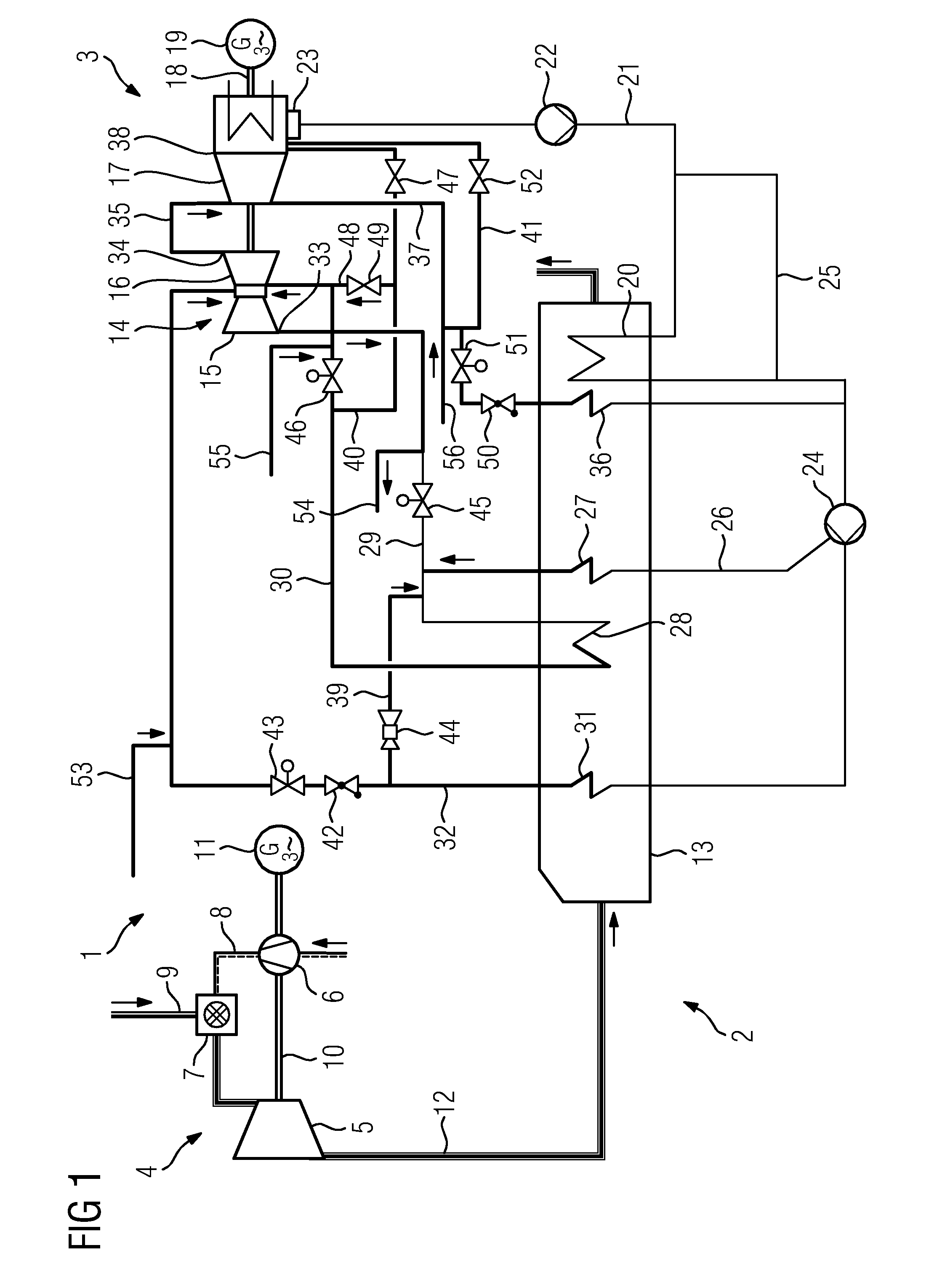
[0025]FIG. 1 shows a schematic diagram by way of an example of a combined cycle power plant 1 having two gas turbine / waste heat steam generator units 2 and a steam turbine system 3, wherein the two gas turbine / waste heat steam generator units can principally be the same. Only the connections from and to the steam turbine system 3 from the first gas turbine / waste heat steam generator unit 2 are shown. As an alternative to the combined-cycle power plant 1 shown, the inventive method is also applicable to a multi-block steam power plant in which the gas turbine / waste heat steam generator units would be replaced by fired steam generator units.

[0026]The gas turbine plant 4 is equipped with a gas turbine 5, a compressor 6 as well as at least one combustion chamber 7 connected between the compressor 6 and the gas turbine 5. Fresh air is sucked, compressed and supplied via the fresh air line to one or more burners of the combustion chamber 7 by means of the compressor 6. The supplied air is...


PUM


Abstract

A method is provided for connecting at least one further steam generator to a first steam generator in a power plant. The power plant includes at least two steam generators and a steam turbine, in which a fluid used to drive the steam turbine is conveyed in a fluid circuit having a plurality of steam systems. The steam systems are assigned individual steam generators and are able to be separated from one another by shut-off valves. The fluid of at least the first steam generator is connected to the steam turbine. The method involves opening the shut-off valve of at least one first steam system of the at least one further steam generator before the steam of the at least one further steam generator has reached approximately the same steam parameters as the steam of the first steam generator, so that steam can flow into the further steam generator.

Description

CROSS REFERENCE TO RELATED APPLICATIONS[0001]This application is the US National Stage of International Application No. PCT / EP2012 / 053852, filed Mar. 7, 2012 and claims the benefit thereof. The International Application claims the benefits of European application No. 11159511.2 EP filed Mar. 24, 2011. All of the applications are incorporated by reference herein in their entirety.FIELD OF INVENTION[0002]The invention relates to a method for rapid connection of at least one further steam generator to a first steam generator in a power plant. The invention further relates to the use of the method in a combined-cycle power plant and in a steam power plant.BACKGROUND OF INVENTION[0003]In a power station in which two or more steam generators are connected to a steam turbine, for running turbines alongside one another or connection of a second or third steam generator the steam systems must be brought to approximately the same the steam states (pressure, temperature) to enable the systems ...

Claims


Application Information

Patent Timeline
Patent Type & Authority Applications(United States)
IPC IPC(8): F01K3/24F01K13/02
CPCF01K3/24F01K13/02F01K13/006F01K23/10Y02E20/16F01K13/00
Inventor HERMSDORF, CHRISTIANMIGL, MATTHIASPETERS, GEORGSCHMID, ERICHSCHOTTLER, MICHAEL
Owner SIEMENS ENERGY GLOBAL GMBH & CO KG
Learn More