Examination of porosity by NMR and intrusion porosimetry

a porosity and intrusion porosimetry technology, applied in the field of nmr and intrusion porosimetry, can solve the problems of affecting the scale and hindering the use of relaxation time, and achieve the effect of increasing the applied pressur

Active Publication Date: 2014-01-02
SCHLUMBERGER TECH CORP
View PDF2 Cites 23 Cited by
  • Summary
  • Abstract
  • Description
  • Claims
  • Application Information

AI Technical Summary

Problems solved by technology

However, this use of relaxation time is hindered by a lack of knowledge regarding the relaxivity, which affects the scale of the results.

Method used


Image

  • Examination of porosity by NMR and intrusion porosimetry
  • Examination of porosity by NMR and intrusion porosimetry

Examples


Embodiment Construction

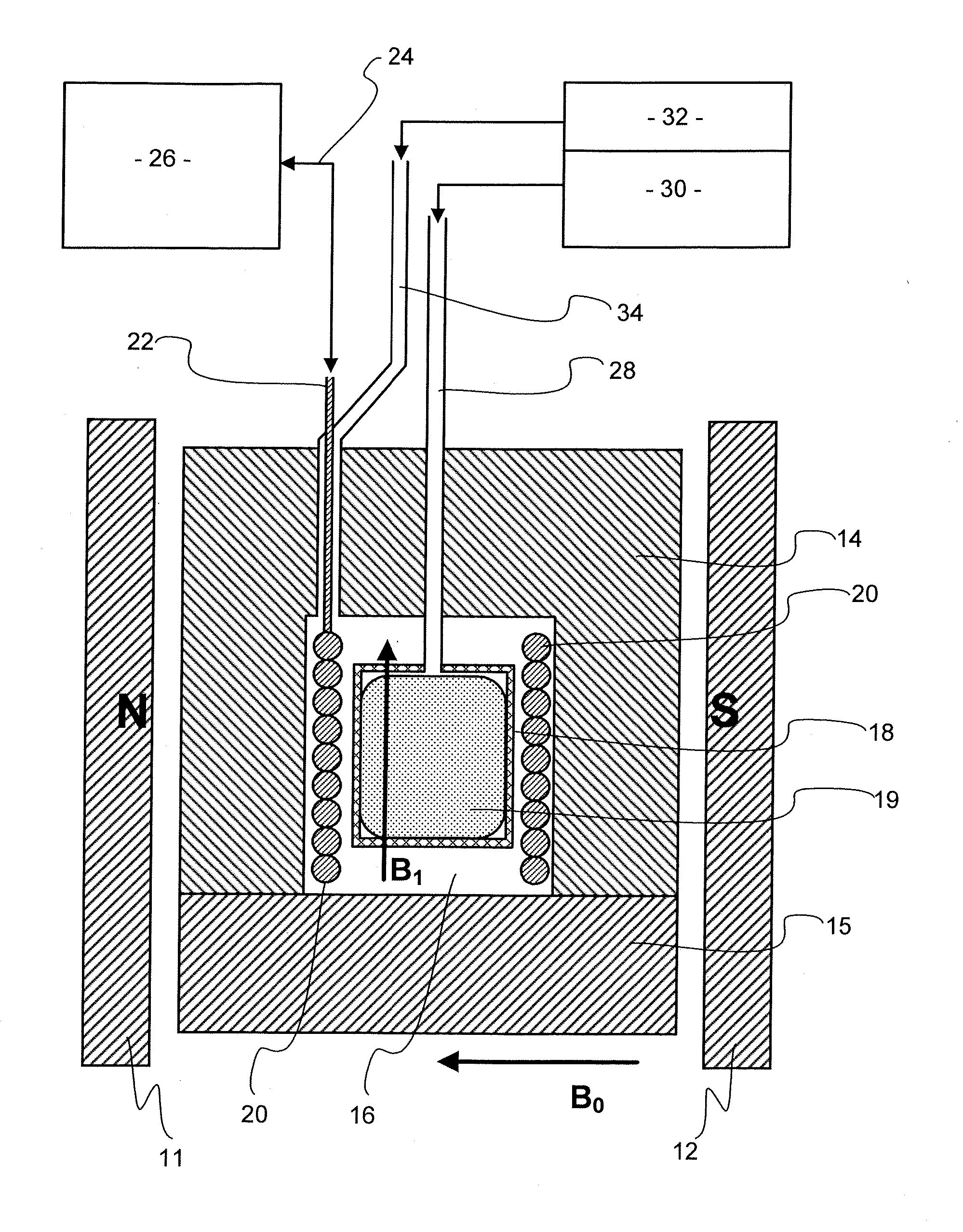
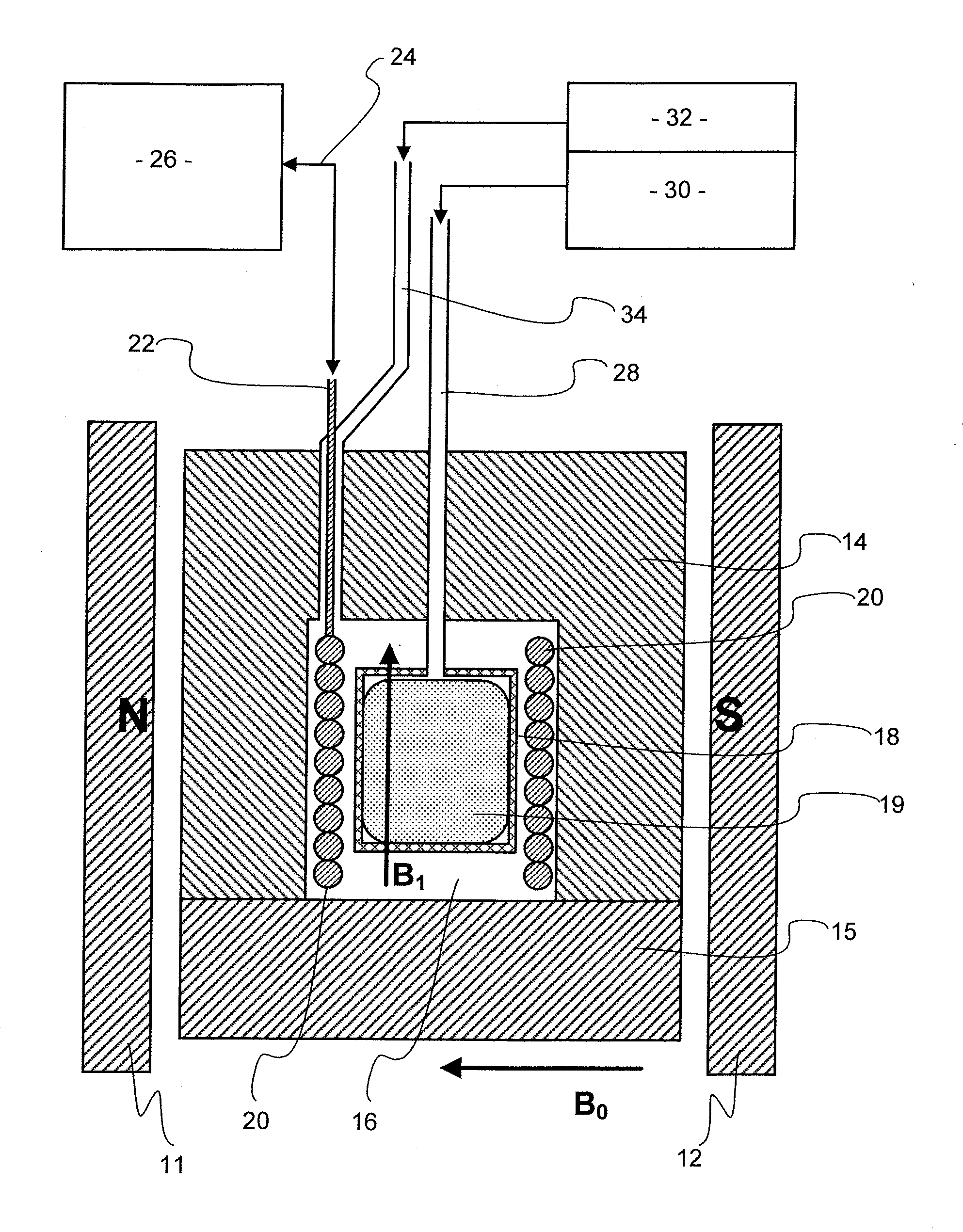
[0021]The apparatus shown in the drawing has a pair of permanent magnets 11, 12 arranged on a common axis facing each other but spaced apart so that there is a static magnetic field between them as indicated by the arrow B0. The magnetic field B0 extends from a S pole piece provided by magnet 12 to a N pole piece provided by magnet 11. In this illustration the magnets 11, 12 are positioned so that the static magnetic field B0 is horizontal. However, the apparatus could be placed at some other orientation if convenient. Both permanent magnets 11, 12 may be made of rare earth compounds to give a high magnetic field. Specifically, they may possibly be neodymium iron boron (NdFeB) magnets which can be manufactured in the required shapes or assembled from smaller blocks. The permanent magnets 11, 12 should desirably provide a magnetic field B0 which is uniform within the space between the magnets.

[0022]A pressure vessel, which is formed in two parts 14, 15 secured together so as to allow...


PUM

PropertyMeasurementUnit
skin depthaaaaaaaaaa
pore diameteraaaaaaaaaa
pressureaaaaaaaaaa

Abstract

Properties of a porous solid sample 19, which may be a core of rock taken from below ground are carried out using apparatus which performs both nuclear magnetic resonance (NMR) and porosimetry measurements. The apparatus has a magnet 11,12 providing a magnetic field and a radio frequency coil 20 for transmitting and / or receiving electromagnetic radiation so as to bring about NMR in the magnetic field, a pressure vessel 14, 15 to hold a sample 19 within the magnetic field, a supply of a non-wetting liquid connected to the vessel, means to apply pressure to the non-wetting liquid to force liquid into pores of the sample 19 means to measure applied pressure of the non-wetting liquid and means to measure volume thereof taken up by the sample. The pressure of non-wetting liquid may be increased in steps, using intruded liquid volume at each step to give a measurement of pore throat size using NMR at each step to give a measure of pore size such as diameter of equivalent sphere. The non-wetting liquid may be mercury and NMR may observe the Knight shift of 99 Hg.

Description

FIELD OF THE INVENTION[0001]This invention is concerned with the determination of properties of pores in porous solids and thus concerns testing of materials. The invention is not limited to specific reasons for testing nor to samples of specific origin, but it may be applied to porous rock cores collected as samples underground whilst drilling. The collection of such samples and their examination may be done in connection with exploration for, or exploitation of, hydrocarbons in underground reservoirs. It is also possible that it may be done in connection with exploration for, or utilisation or management of underground water, or in connection with schemes for the storage of captured carbon dioxide.BACKGROUND OF THE INVENTION[0002]There are many circumstances where it is desired to make measurements of the properties of pores in a porous material. One such is the testing of samples of porous rock.[0003]It is conventional practice when drilling through underground rock to drill arou...

Claims


Application Information

Patent Timeline
Patent Type & Authority Applications(United States)
IPC IPC(8): G01N24/08
CPCG01N24/081G01N15/088G01N15/0886G01N2015/0866
Inventor MITCHELL, JONATHANFORDHAM, EDMUND
Owner SCHLUMBERGER TECH CORP
Why Eureka
Try Eureka