Duty cycle correction within an integrated circuit

a technology of duty cycle correction and integrated circuit, which is applied in the direction of pulse generator, pulse duration/width modulation, pulse manipulation, etc., can solve the problems of continuous consumption of power during the operation of the integrated circuit by the analog duty cycle correction circuitry, and the difficulty of the integrated circuit operation, so as to reduce the settle time and prolong the first use settle time

Inactive Publication Date: 2014-01-02
ARM LTD
View PDF4 Cites 16 Cited by
  • Summary
  • Abstract
  • Description
  • Claims
  • Application Information

AI Technical Summary

Benefits of technology

[0010]The present invention provides the ability for duty cycle correcting circuitry controlled by a digital correction value to be used to track and correct for the drift in the duty cycle of a digital signal that can occur during operation, e.g. due to changes in temperature and / or voltage. Thus, the variations in manufacture of an individual integrated circuit which result in duty cycle variation can be corrected at start up and then other time-varying variations can be corrected with the periodic detection of whether the duty cycle has drifted outside of a threshold range and the corresponding adjustment of the digital correction value to bring the duty cycle back within the threshold range.
[0011]The digital correction value may be stored within a register. Thus, when the integrated circuit starts its operation, the value stored within that register may be read and used to control the duty cycle without a calibration process being required thereby reducing the settle time associated with duty cycle correction. Upon the first use of the integrated circuit a default value may be used within this register and a longer first use settle time may be tolerated. The digital correction value may be stored into the register upon first operation and / or upon a reset to the duty cycle correcting circuitry.

Problems solved by technology

If the duty cycle varies from the 50% duty cycle, then this can cause difficulty in the operation of the integrated circuit.
Such circuits have a number of disadvantages, such as a finite settle time upon every start up during which the integrated circuit may not be released to operate correctly and the continuous consumption of power during operation of the integrated circuit by the analog duty cycle correction circuitry.

Method used


Image

  • Duty cycle correction within an integrated circuit
  • Duty cycle correction within an integrated circuit
  • Duty cycle correction within an integrated circuit

Examples


Embodiment Construction

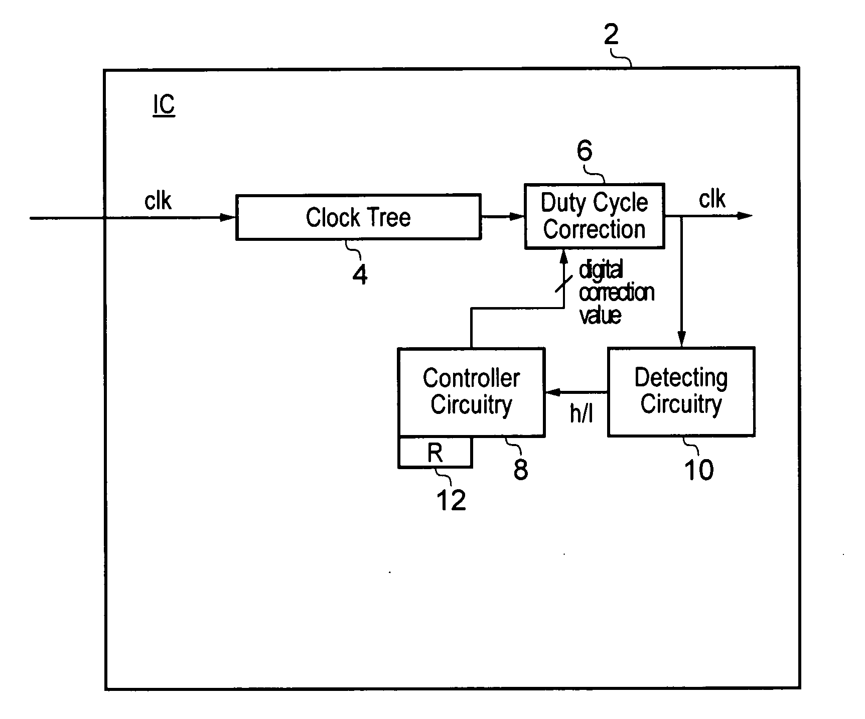
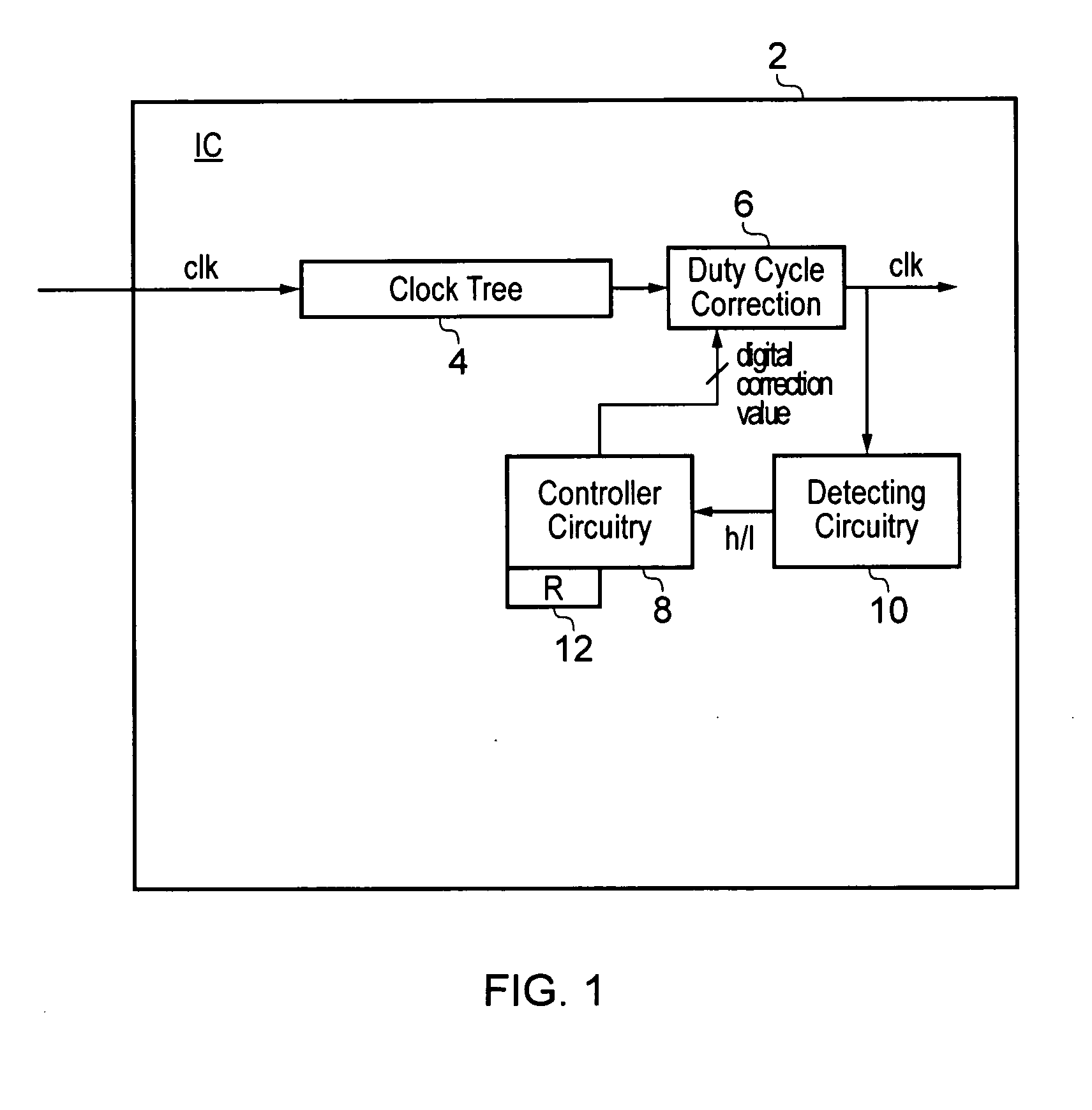
[0043]FIG. 1 schematically illustrates an integrated circuit 2 operating with a digital signal in the form of a clock signal clk that is distributed by clock tree circuitry 4. In order to correct the duty cycle of the clock signal clk to a target duty cycle (e.g. 50%), there is provided duty cycle correction circuitry 6 which receives a duty cycle uncorrected clock signal and outputs a duty cycle corrected clock signal. The duty cycle correction circuitry 6 operates under control of a digital correction value which sets the magnitude and direction of the duty cycle correction applied by the duty cycle correction circuitry 6. This digital correction value is generated by controller circuitry 8. The controller circuitry 8 determines what magnitude the digital correction value should have in response to indications provided to it by detecting circuitry 10 which also measures whether the clock signal output from the duty cycle correction circuitry 6 has a duty cycle which is higher or l...


PUM


Abstract

An integrated circuit 2 operates using a digital signal having a duty cycle. Duty cycle correction circuitry 26, 28, 30 operate under control of digital correction values which adjust the duty cycle of the digital signal to a target duty cycle. Periodically, detection of the duty cycle output from the duty cycle correction circuitry 26, 28, 30 is performed to determine whether or not this has drifted outside of a threshold range of duty cycles and if necessary the digital correction value is changed to bring the duty cycle back within the threshold range. The duty cycle correction circuitry 26, 28, 30 employs common mode logic stages 44, 46 and an auxiliary current path 48 which is controlled in its impedance by the digital correction value. The auxiliary current path 48 applies an offset voltage within the common mode logic stage 44 which adjusts the duty cycle of the digital signal represented by the differential signals propagating through the common mode logic stage 44.

Description

BACKGROUND OF THE INVENTION[0001]1. Field of the Invention[0002]This invention relates to the field of integrated circuits. More particularly, this invention relates to the correction of the duty cycle of a digital signal within an integrated circuit.[0003]2. Description of the Prior Art[0004]Integrated circuits typically operate using many digital signals. Examples of such signals include clock signals which are used to regulate and control the processing operations of an integrated circuit. The clock signals typically have the form of a square wave. An ideal square wave will typically have a duty cycle of 50% corresponding to the signal having an equal durations for its high periods and its low periods. The edges in the signal when it transitions from low to high and from high to low are often used as timing points for controlling the operation of the integrated circuit. If the duty cycle varies from the 50% duty cycle, then this can cause difficulty in the operation of the integr...

Claims


Application Information

Patent Timeline
Patent Type & Authority Applications(United States)
IPC IPC(8): H03K3/017
CPCH03K5/1565
Inventor DWIVEDI, SANDEEPVORUGU, MUNISWARA REDDYKUMAR, NIDHIR
Owner ARM LTD
Why Eureka
Try Eureka