Printer

a printing machine and battery technology, applied in the field of printing machines, can solve the problems of operator inability to use up the battery, bad influence on the battery, and discharge state,

Active Publication Date: 2014-01-02
BROTHER KOGYO KK
View PDF2 Cites 15 Cited by
  • Summary
  • Abstract
  • Description
  • Claims
  • Application Information

AI Technical Summary

Benefits of technology

[0011]The present disclosure has an object to provide a printer which can sufficiently use up a battery while preventing an over discharge state without performing an input operation of the battery type by the operator or a detecting operation of the battery type itself on the device side if a plurality of types of batteries is replaced as appropriate and used.
[0015]In the disclosure of the present application, the threshold value for exhaustion determination is switched in a form corresponding to a plurality of types of batteries. Specifically, first, the above described threshold value for exhaustion determination is set by a first setting part to a first threshold value corresponding to a lower limit voltage of a primary battery (an alkali manganese battery provided with a high voltage characteristic before the voltage drops and a low voltage characteristic at a print load after the voltage drops in the above described example. The same applies to the following) provided with a first load voltage characteristic and a first after-drop voltage characteristic. As a result, if the primary battery is actually accommodated in the battery accommodating part and used, the notification processing is correctly executed in the vicinity of the lower limit voltage, and thus the primary battery can be sufficiently used up.
[0017]Then, in the disclosure of the present application, attention is paid to a difference in a range of the voltage characteristic before the above described voltage drop (specifically the load voltage characteristic under a condition that a predetermined constant load is applied, for example, a standby voltage, a feed voltage, a voltage in uniform printing and the like) between the primary battery and the secondary battery when exhaustion progresses gradually, a threshold value for constant load voltage determination for the above described switching is stored by a second setting part. That is, the second setting part stores the threshold value for constant load voltage determination so that it becomes smaller than a range of the above described load voltage characteristic of the first battery (first load voltage characteristic) and is included in a range of the above described load voltage characteristic of the secondary battery (second load voltage characteristic). Then, if it is determined by a constant load voltage determining part that the output voltage value of the battery has reached the threshold value for constant load voltage determination, a threshold value changing part changes the above described first threshold value set as the above described threshold value for exhaustion determination to the second threshold value corresponding to a recommended final voltage of the secondary battery. Since the threshold value for constant load voltage determination takes a value out of the range of the first load voltage characteristic as described above, if the primary battery is accommodated in the battery accommodating part and used as described previously, the output voltage value of the battery does not reach the threshold value for constant load voltage determination, and the above described threshold value change is not made. Therefore, only if the secondary battery is accommodated in the battery accommodating part, the threshold value is changed to the above described second threshold value when the above described second load voltage characteristic lowers to the threshold value for constant load voltage determination. As a result, since the notification processing is correctly executed in the vicinity of the recommended final voltage of the secondary battery, the secondary battery can be sufficiently used up while the over discharge state is prevented.
[0018]As described above, according to the disclosure of the present application, if the plurality of types of batteries are appropriately replaced and used, it is possible to use up the battery sufficiently while preventing the over discharge state without performing an input operation of the battery type by the operator or a detection operation of the battery type itself on the device side.

Problems solved by technology

Therefore, when the above described threshold value used for exhaustion determination is set uniformly in accordance with the lower limit voltage on the use of the alkali manganese battery, for example, if the nickel hydrogen battery is actually used, the voltage falls under a recommended final voltage of the nickel hydrogen battery, which may cause an over discharge state in some cases to give a bad influence to the battery.
On the contrary, when the above described threshold value is set uniformly in accordance with a recommended final voltage of the nickel hydrogen battery, if the alkali manganese battery is actually used, determination of exhaustion is made although the voltage has not reached the lower limit voltage of the alkali manganese battery and exhaustion has not progressed so much, and an operator cannot use up the battery until sufficient discharge has been made.
In this case, if the type of the battery is falsely detected, an inappropriate threshold value is set, and as a result, there is a problem that a degree of exhaustion of the battery cannot be determined with high accuracy.
However, in this case, the input operation by the operator is needed at each time of use, which is troublesome, and there may be a possibility that the operator erroneously inputs a type different from an actual battery type.
If a secondary battery is exhausted and the output voltage value lowers to some extent, further discharge from the battery becomes over discharge in some cases and badly affects the battery itself.

Method used


Image

  • Printer
  • Printer
  • Printer

Examples


Embodiment Construction

[0034]An embodiment of the present disclosure will be described below by referring to the attached drawings.

[0035]In the present embodiment, the present disclosure is applied to a print label producing device 1 as a printer. This print label producing device 1 produces a print label L (See FIG. 5 which will be described later) corresponding to a printed object by cutting a label tape with print on which a desired print has been applied to a predetermined length.

[0036]

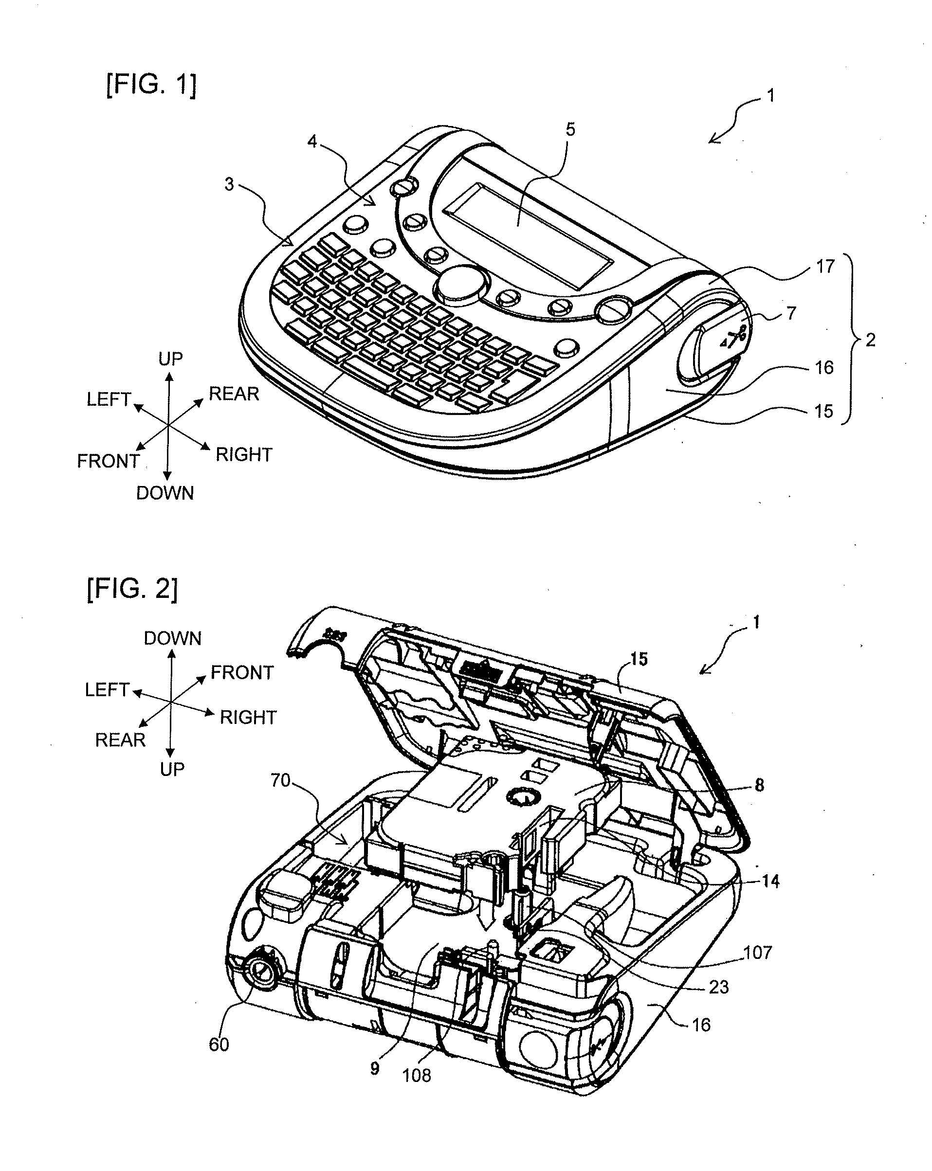
[0037]First, an outline configuration of this print label producing device 1 will be described by using FIG. 1. In the present embodiment, the terms, front, rear, left, right, up, and down of the print label producing device 1 refer to the directions illustrated in FIGS. 1, 2 and the like.

[0038]As illustrated in FIGS. 1 and 2, a housing 2 of the print label producing device 1 is composed of a lower cover 15 constituting a lower surface of the device, a lateral cover 16 constituting the side face of the device, and an up...


PUM


Abstract

The disclosure discloses a printer. The printer comprises a feeder, a driving device, a printing head, a power feed device configured to supply electric power, a battery accommodating part configured to selectively accommodate either one of a primary battery and a secondary battery, a voltage detecting device, an exhaustion determining part configured to determine whether or not a print load voltage has reached a threshold value for exhaustion determination, a notification part configured to perform predetermined notification processing, a first setting part configured to set the threshold value to a first threshold value, a second setting part configured to store a threshold value for constant load voltage determination, a constant load voltage determining part configured to determine whether or not the constant load voltage has reached the threshold value, and a threshold value changing part configured to change the first threshold value to a second threshold value.

Description

CROSS-REFERENCE TO RELATED APPLICATION[0001]The present application claims priority from Japanese Patent Application No. 2012-147084, which was filed on Jun. 29, 2012, the disclosure of which is incorporated herein by reference in its entirety.BACKGROUND[0002]1. Field[0003]The present disclosure relates to a printer driven by a battery.[0004]2. Description of the Related Art[0005]Printers operating by using a battery have been already proposed so that a user can casually use printers, for example. In this case, repetition of production of printed objects and repetition of discharge of a battery gradually exhaust the battery. Whether the battery has exhausted or not can be determined by setting a predetermined threshold value, for example, and by checking if an output voltage value of the battery changing over time has lowered to the threshold value or not.[0006]Here, there is a case where a plurality of types of batteries is appropriately replaced and used in one and the same printe...

Claims


Application Information

Patent Timeline
Patent Type & Authority Applications(United States)
IPC IPC(8): B41J2/35
CPCB41J2/35B41J3/36B41J2/32B41J3/4075G01R31/3647H02J7/00306H02J7/00
Inventor MIYABAYASHI, HIROKAZU
Owner BROTHER KOGYO KK
Why Eureka
Try Eureka