Protection circuit

a protection circuit and circuit technology, applied in the field of protection circuits, can solve problems such as damage to integrated circuits including protection circuits, and achieve the effect of preventing damag

Active Publication Date: 2014-01-02
ALPS ALPINE CO LTD
View PDF3 Cites 3 Cited by
  • Summary
  • Abstract
  • Description
  • Claims
  • Application Information

AI Technical Summary

Benefits of technology

[0003]The present disclosure relates to protection circuits, which may prevent damage on a circuit, and it particularly relates to a protection circuit, which may prevent damage on a circuit due to a reverse connection of a power supply thereto.

Problems solved by technology

Occurrence of such a voltage drop prevents application of a proper reverse bias to a PN junction present in the protection circuit 2, which facilitates flow of unnecessary current and may damage the integrated circuit including the protection circuit 2.

Method used


Image

  • Protection circuit
  • Protection circuit
  • Protection circuit

Examples


first embodiment

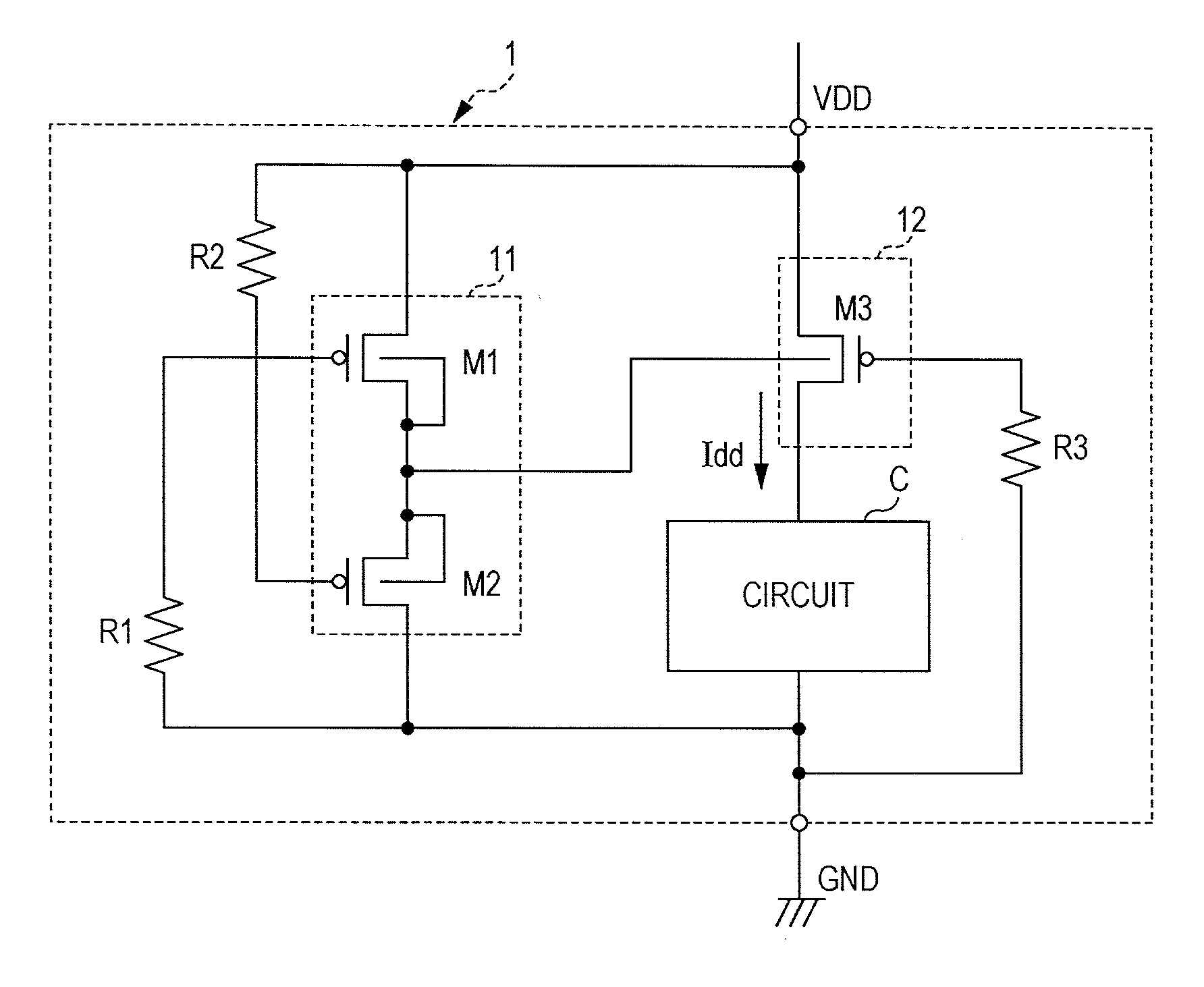
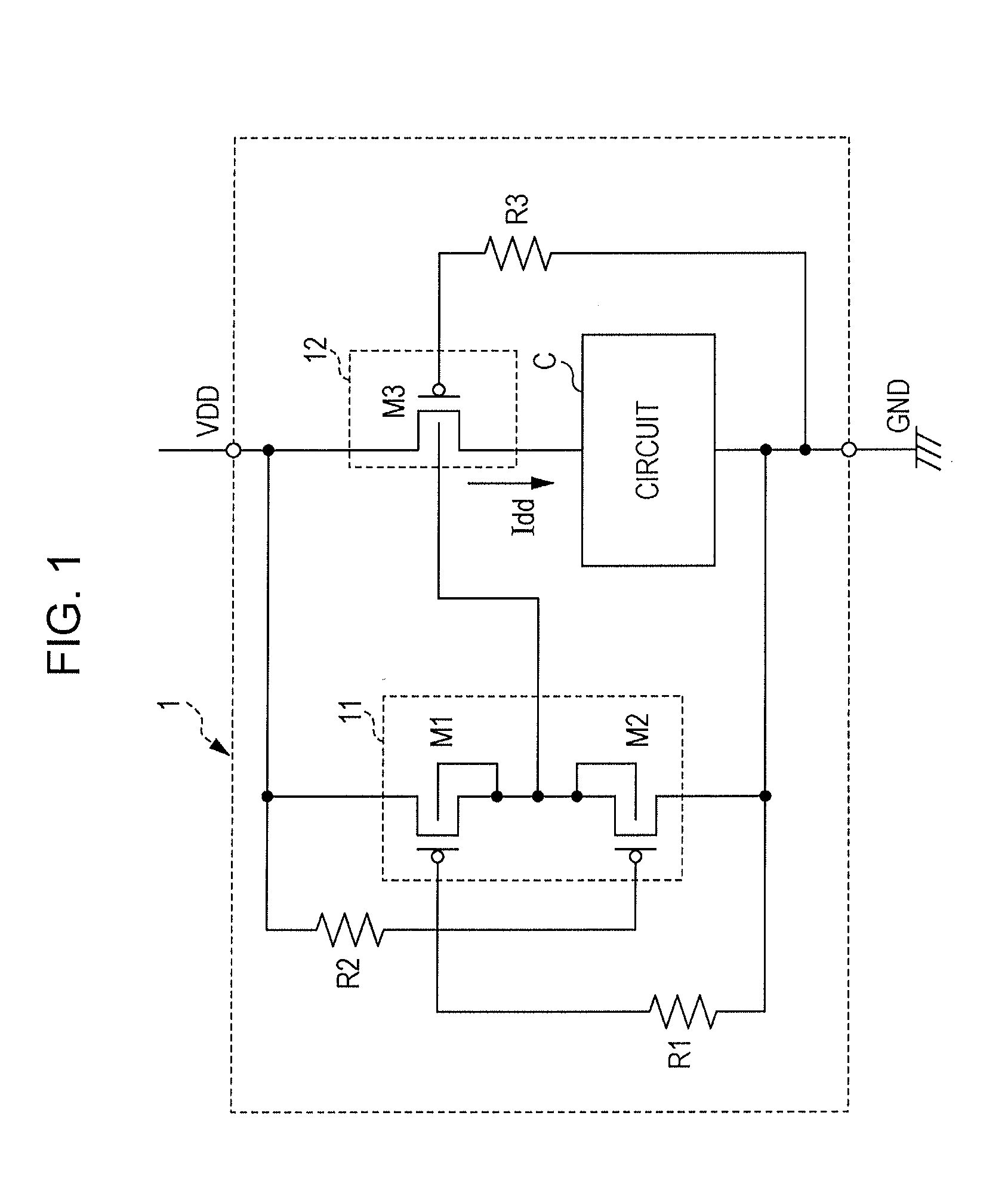
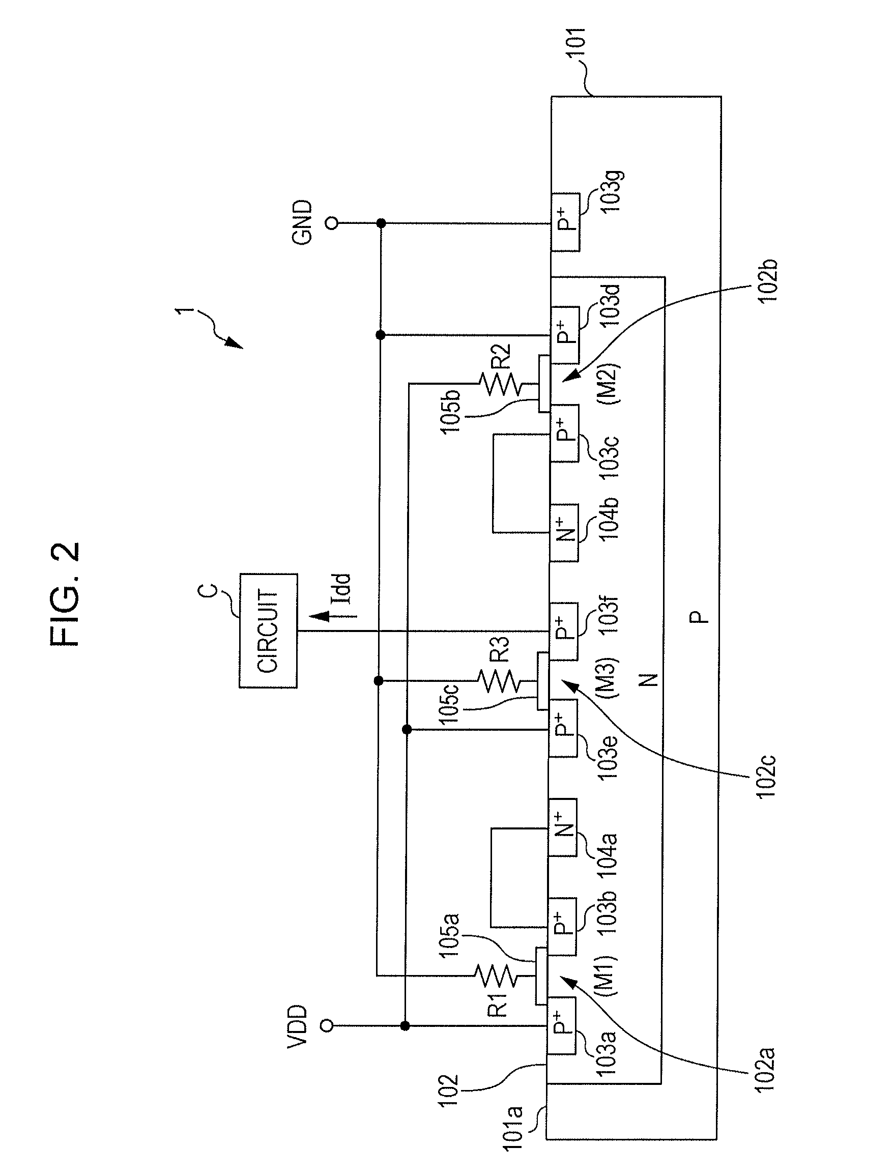
[0024]FIG. 1 is a circuit diagram illustrating a configuration of an apparatus including a protection circuit 1 according to a first embodiment. FIG. 2 is a schematic diagram illustrating an example of an element structure of the protection circuit 1 according to this embodiment. As illustrated in FIG. 1, the protection circuit 1 of this embodiment includes a power supply terminal VDD, a ground terminal GND, three transistors M1 to M3, and three resistances R1 to R3. A high level potential is supplied to the power supply terminal VDD forward connected to a power supply (DC power supply), not illustrated, and a low level potential is supplied to the ground terminal GND forward connected to the power supply.

[0025]The three transistors M1 to M3 are all P-channel type MOSFETs. A control unit 11, which controls a potential of an N-well 102 (see FIG. 2), which will be described below, includes the transistor (first transistor) M1 and transistor (second transistor) M2. A supply unit 12, wh...

second embodiment

[0045]According to a second embodiment, a protection circuit will be described which is different from the first embodiment. FIG. 3 is a schematic diagram illustrating an example of an element structure of a protection circuit 1a according to this embodiment. The protection circuit 1a according to this embodiment is the same as the protection circuit 1 according to the first embodiment except for its element structure. Since the circuit configuration of the protection circuit 1a is the same as the protection circuit 1 illustrated in FIG. 1, the detail description on the circuit configuration will be omitted.

[0046]As illustrated in FIG. 3, the protection circuit 1a of this embodiment is provided on a P-type substrate 111. N-wells 112 and 113 containing donors is formed on a surface 111a side of the substrate 111 by an ion implantation method, for example. In the N-well 112, high concentration P-type regions 114a to 114d containing a high concentration of acceptors and a high concentr...


PUM


Abstract

A protection circuit includes a power supply terminal, a ground terminal, a control unit connected to the power supply terminal and the ground terminal, and a supply unit connected to the power supply terminal and the ground terminal, for preventing application of voltage in a reverse direction to a circuit unit having a predetermined function. In this case, the control unit generates a control potential, which controls the control unit and the supply unit in accordance with a potential supplied from the power supply terminal and a potential supplied from the ground terminal. The supply unit is configured to be capable of supplying current to a circuit unit connected to a subsequent stage on the basis of a potential supplied from the power supply terminal, a potential supplied from the ground terminal, and the control potential generated by the control unit.

Description

CLAIM OF PRIORITY[0001]This application claims benefit of priority to Japanese Patent Application No. 2012-145279 filed on Jun. 28, 2012, which is hereby incorporated by reference in its entirety.BACKGROUND[0002]1. Field of the Disclosure[0003]The present disclosure relates to protection circuits, which may prevent damage on a circuit, and it particularly relates to a protection circuit, which may prevent damage on a circuit due to a reverse connection of a power supply thereto.[0004]2. Description of the Related Art[0005]A vehicle-mounted integrated circuit may include a protection circuit for preventing damage due to reverse connection of a power supply such as a battery (see Japanese Unexamined Patent Application Publication No. 5-152526). FIG. 4 illustrates a circuit configuration of an integrated circuit including such a protection circuit. A protection circuit 2 illustrated in FIG. 4 includes two P-channel type MOSFETs (Metal-Oxide-Semiconductor Field-Effect Transistors) Q3 an...

Claims


Application Information

Patent Timeline
Patent Type & Authority Applications(United States)
IPC IPC(8): H02H3/00
CPCH02H3/003H03K19/00315
Inventor SAWATAISHI, TOMOYUKILIKURA, AKIHISANAKAO, KIMIHIROASAO, AKIRA
Owner ALPS ALPINE CO LTD
Why Eureka
Try Eureka