Ceramic matrix composite and metal attachment configurations

a ceramic matrix and metal attachment technology, applied in the field of turbines, can solve the problems of abrasion, wear of metallic hardware by hard, lack of load distribution in the cmc, and difficulty in attaching metal and ceramic matrix composites, and achieve the effect of minimizing bolt growth

Inactive Publication Date: 2014-01-02
GENERAL ELECTRIC CO
View PDF4 Cites 20 Cited by
  • Summary
  • Abstract
  • Description
  • Claims
  • Application Information

AI Technical Summary

Benefits of technology

[0006]According to another exemplary embodiment of the present disclosure, a ceramic matrix composite and metal attachment configuration is provided. The ceramic matrix composite and metal attachment configuration includes a metal plate having a metal plate aperture. The ceramic matrix composite and metal attachment configuration includes a ceramic matrix composite plate adjacent the metal plate and including a ceramic matrix composite plate aperture aligned with the metal plate aperture. The ceramic matrix composite and metal attachment configuration includes a metal bolt having a first end, a second end, and a channel running therethrough. The second end of bolt is operable to fit into the aligned ceramic matrix composite plate aperture, and metal aperture to attach the ceramic matrix composite plate and the metal plate. The ceramic matrix composite and metal attachment configuration includes a nut adjacent to the metal plate and operable to receive the second end of the bolt. The channel of the metal bolt minimizes growth of the bolt relative to the ceramic matrix composite plates due to mismatch of coefficient of thermal expansion between the metal bolt and the metal plate and the ceramic matrix composite plate.

Problems solved by technology

Two disadvantages associated with attaching a CMC to metallic hardware are the wear of the metallic hardware by the hard, abrasive ceramic material surface, and the lack of load distribution in the CMC.
Additionally, differences between the coefficients of thermal expansion between the metal and ceramic matrix composite make attaching metal and ceramic matrix composites challenging.

Method used


Image

  • Ceramic matrix composite and metal attachment configurations
  • Ceramic matrix composite and metal attachment configurations
  • Ceramic matrix composite and metal attachment configurations

Examples


Embodiment Construction

[0016]Provided are ceramic matrix composite and metal attachment configurations to attach ceramic matrix composites to metal components having different coefficients of thermal expansions.

[0017]One advantage of an embodiment of the present disclosure includes providing an attachment configuration for attaching CMC components that have a low thermal expansion coefficient (αCMC) to metal component that have a high thermal expansion coefficient (αmetal) relative to CMC components.

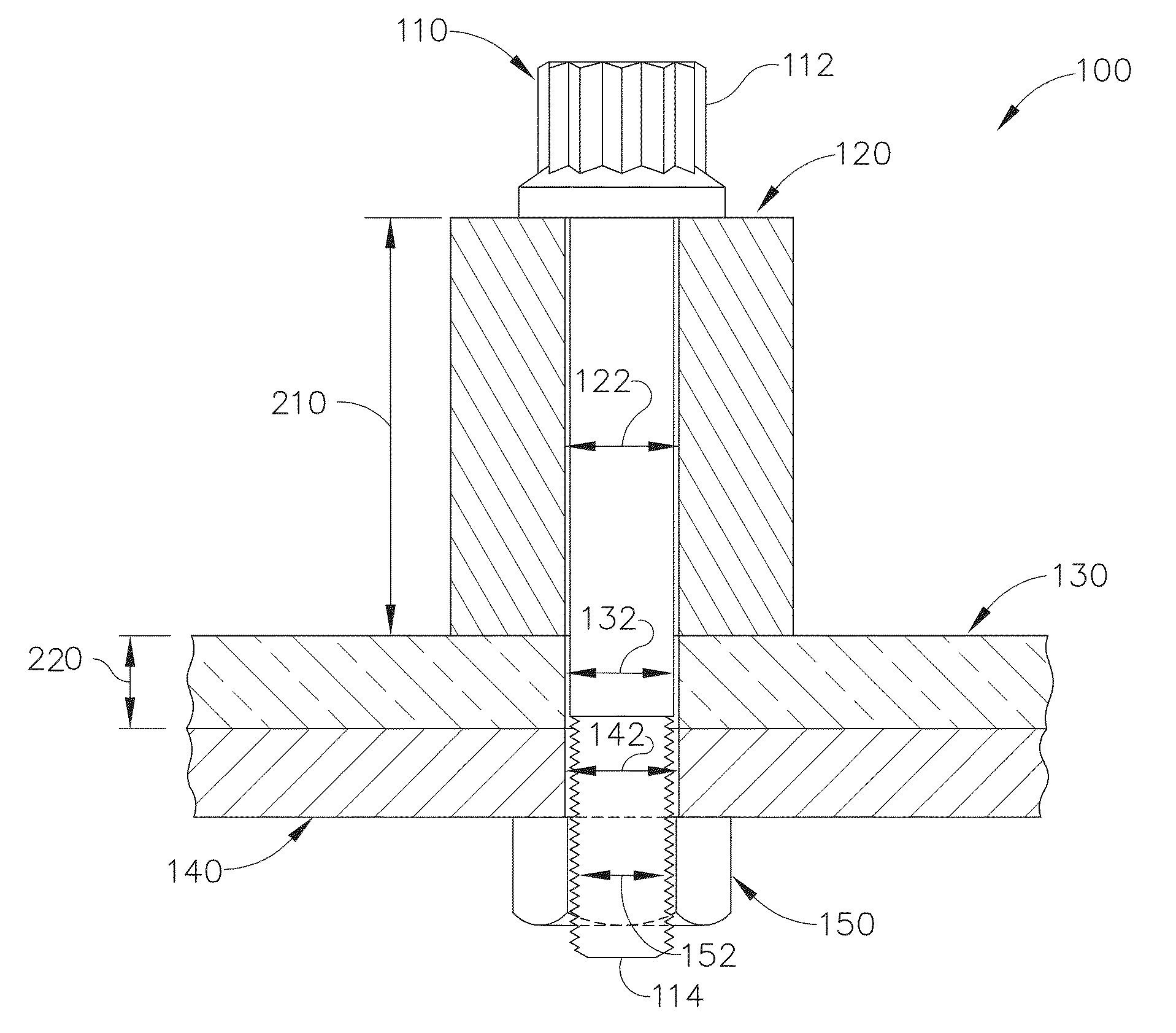
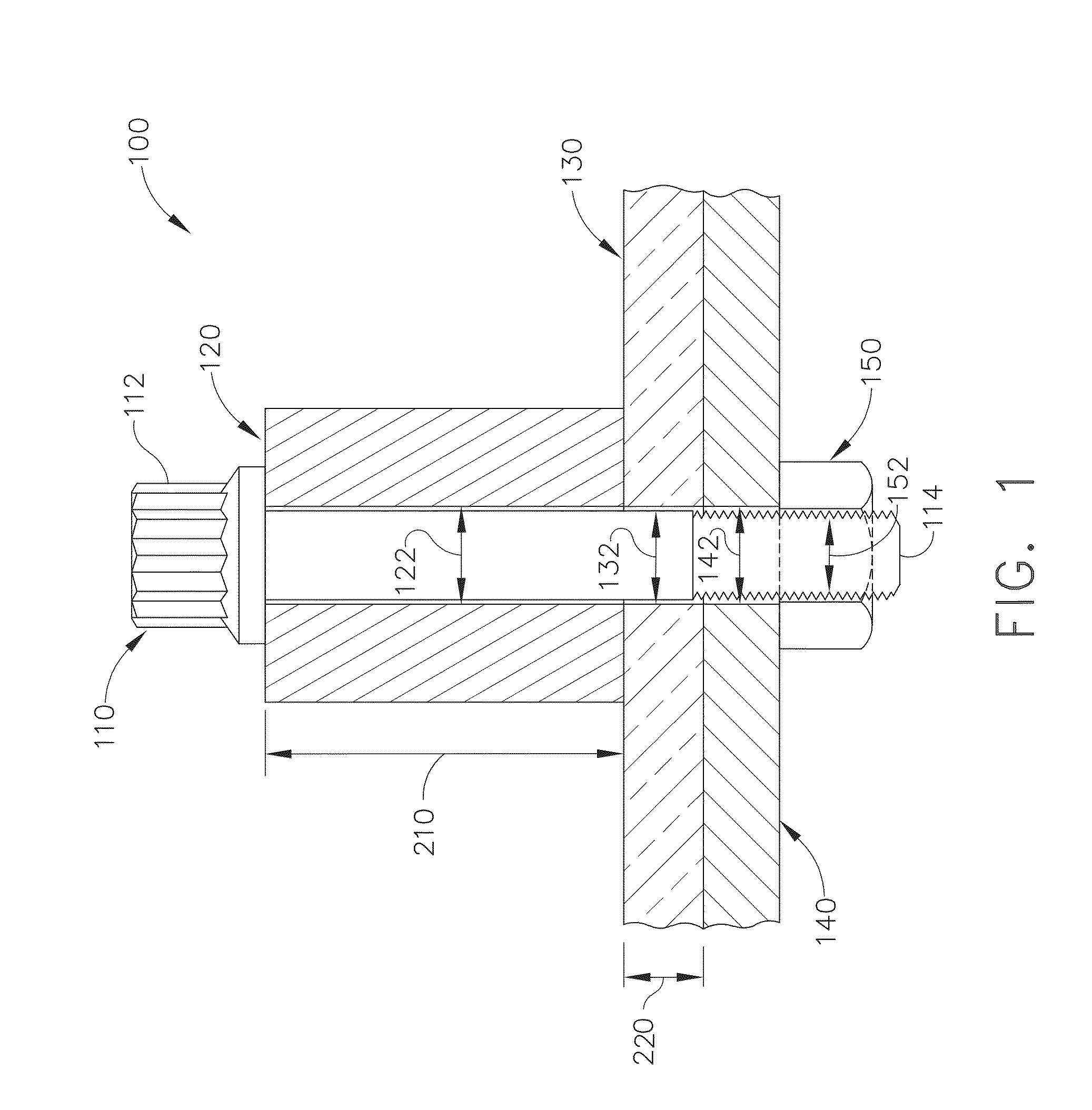
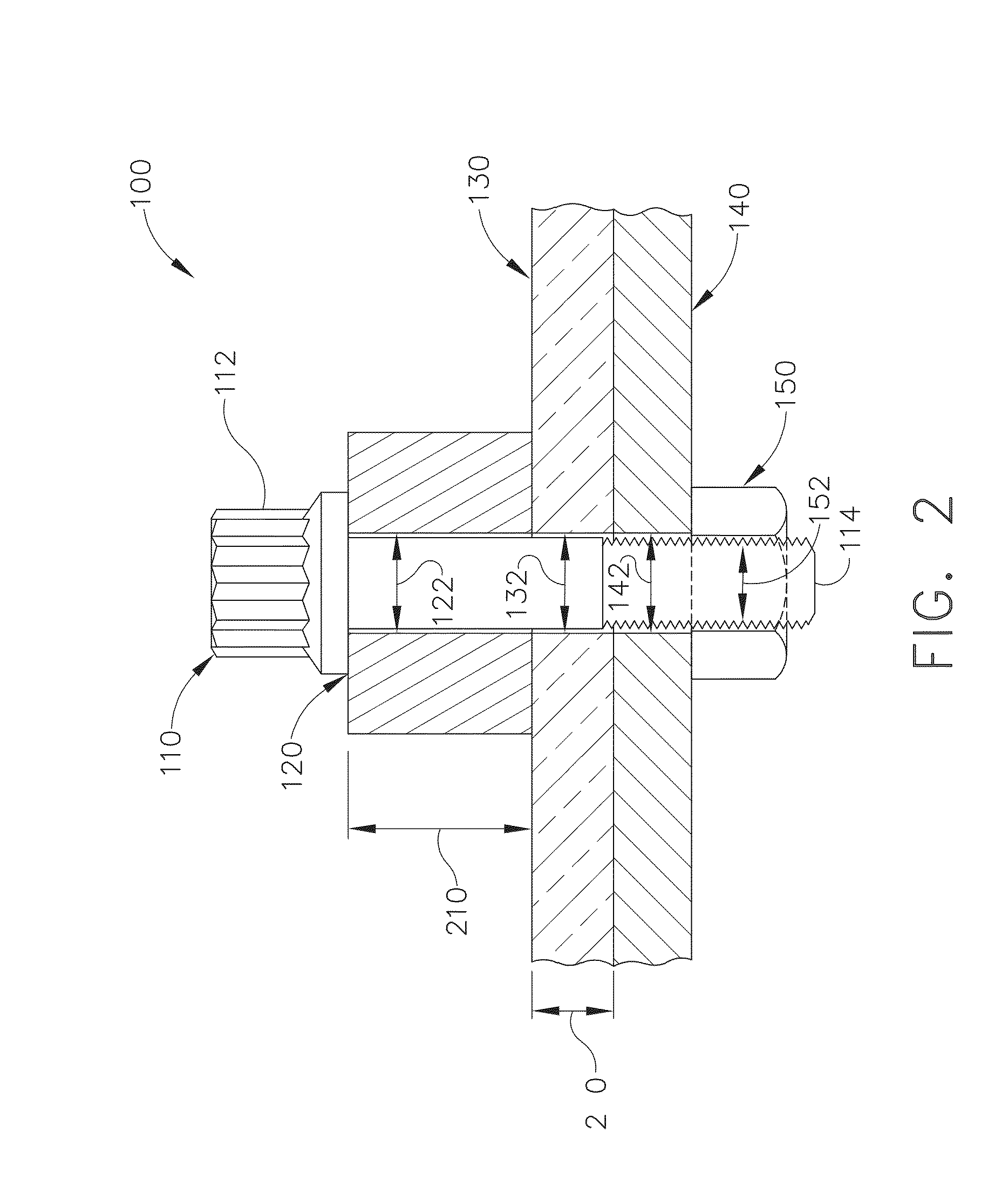
[0018]According to one embodiment a ceramic matrix composite and metal attachment configuration including a metal plate and a ceramic matrix composite plate is provided. For example, FIG. 1 is a schematic section view of a ceramic matrix composite and metal attachment configuration 100. Ceramic matrix composite and metal attachment configuration 100 may include a metal plate 140 having a metal plate aperture 142. Metal plate may have a high coefficient of thermal expansion (αmetal), relative to CMC components....


PUM

PropertyMeasurementUnit
coefficient of thermal expansionaaaaaaaaaa
thicknessaaaaaaaaaa
temperatureaaaaaaaaaa

Abstract

A ceramic matrix composite (CMC) and metal attachment configuration is provided. The CMC and metal attachment may include a metal plate, a CMC plate, a spacer, a metal bolt and a nut. Metal plate may include metal plate aperture. CMC plate may be adjacent metal plate and may include CMC plate aperture aligned with metal plate aperture. Spacer may be adjacent to CMC, and spacer may include spacer aperture aligned with metal plate and CMC apertures. Metal bolt may have first and second ends, second end may be operable to fit into aligned spacer, CMC plate, and metal apertures, to attach spacer, CMC plate and metal plate. Nut may be adjacent to metal plate and may be operable to receive second end of bolt. Spacer may allow metal plate, having a high coefficient of thermal expansion, to be attached to CMC plate, having a low coefficient of thermal expansion.

Description

CROSS-REFERENCE TO RELATED APPLICATIONS[0001]This patent application claims the benefit of U.S. Provisional Patent Application Ser. No. 61 / 666,826 filed on Jun. 30, 2012, and entitled “CERAMIC MATRIX COMPOSITE AND METAL ATTACHMENT CONFIGURATIONS,” the disclosure of which is incorporated by reference as if fully rewritten herein.FIELD OF THE INVENTION[0002]The present invention relates generally to turbines. More specifically, to attaching ceramic matrix composites (CMC) in gas turbines to metal components with a bolt.BACKGROUND OF THE INVENTION[0003]Generally, ceramic matrix composite turbine components require attachment to adjoining metallic hardware and / or metallic surfaces. Two disadvantages associated with attaching a CMC to metallic hardware are the wear of the metallic hardware by the hard, abrasive ceramic material surface, and the lack of load distribution in the CMC. Additionally, differences between the coefficients of thermal expansion between the metal and ceramic matri...

Claims


Application Information

Patent Timeline
Patent Type & Authority Applications(United States)
IPC IPC(8): F16B35/00
CPCF16B35/00F16B5/0241F16B5/02F16B5/025
Inventor GROOMS, II, JAMES HAMILTON
Owner GENERAL ELECTRIC CO
Why Eureka
Try Eureka