Electric compressor

a compressor and electric technology, applied in the direction of piston pumps, positive displacement liquid engines, dynamo-electric converter control, etc., can solve the problems of difficult to maintain comfortable air-conditioning in vehicles, and achieve the effect of reducing the time required

Inactive Publication Date: 2014-01-09
PANASONIC CORP
View PDF7 Cites 7 Cited by
  • Summary
  • Abstract
  • Description
  • Claims
  • Application Information

AI Technical Summary

Benefits of technology

[0011]When the power source is disconnected, the supply of current from the power source to the capacitor is terminated. In response, the capacitor starts discharging the charges stored therein. The charge that is discharged flows to the load resistor. Since the load resistor is provided closer to the power source connecting section than the current detecting section, the direction of the flow of charges toward the load resistor is opposite to the direction of the flow when the power source is connected. According to the present invention, it is possible to detect that the power source is disconnected, based on the direction of current, before a voltage value decreases to a predetermined voltage value. Therefore, it is possible to reduce the time necessary for detecting that the power source is disconnected, and to prevent a user from being electrified by voltage remaining in the capacitor.

Problems solved by technology

Accordingly, if the engine-driven compressors are used, it is difficult to maintain comfortable air-conditioning in the vehicles.

Method used


Image

  • Electric compressor
  • Electric compressor
  • Electric compressor

Examples


embodiment

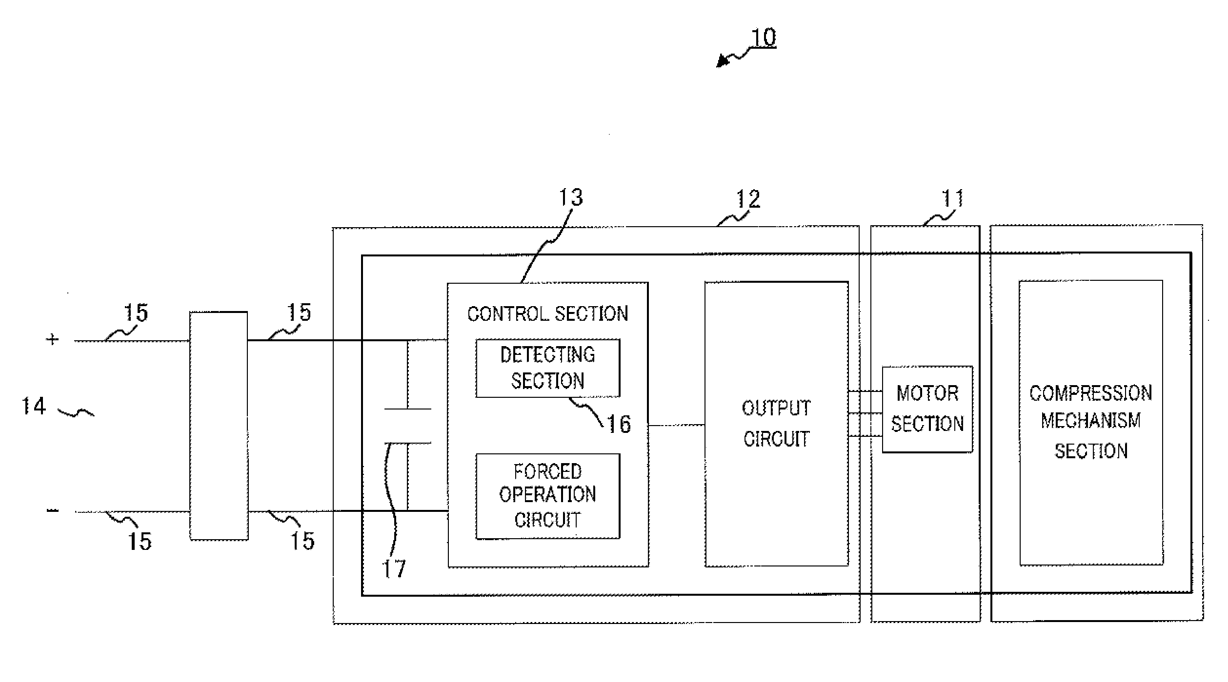
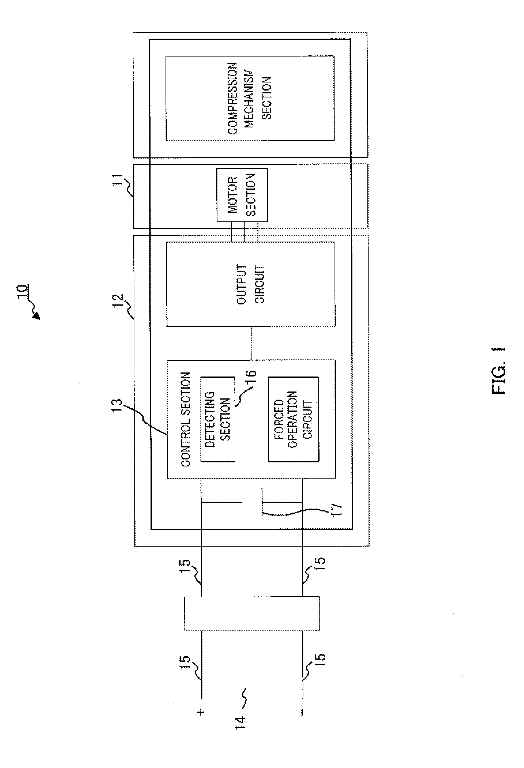
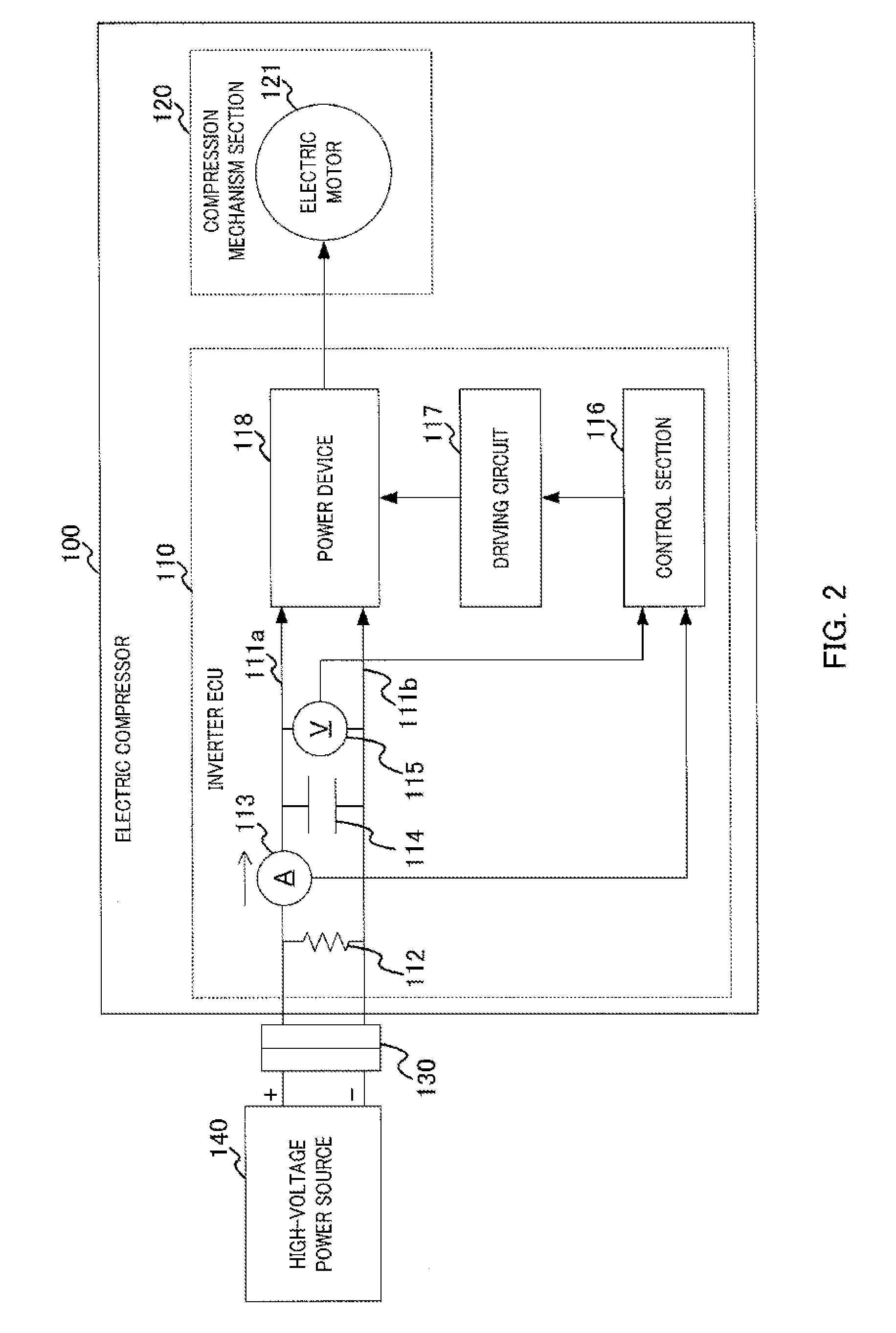
[0020]FIG. 2 is a block diagram illustrating a configuration of electric compressor 100 according to an embodiment of the present invention. Electric compressor 100 includes inverter ECU (electronic control unit) 110 and compression mechanism section 120. Inverter ECU 110 is connected to power source connector 130. Power source connector 130 (corresponding to the power source Connecting section) is detachably attached to high-voltage power source 140 that generates DC power (hereafter simply referred to as “power source). Compression mechanism section 120 includes electric motor 121, and compresses a refrigerant by driving electric motor 121.

[0021]Inverter ECU 110 includes control section 116, driving circuit 117, and power device 118. Load resistor 112, current detecting section 113, capacitor 114, and voltage detecting section 115 are connected, in order, to power line 111 from the side of the power source connector 130. Power line 111 connects power source connector 130 and power...


PUM


Abstract

A capacitor (114) is provided between a power supply line (111a) and a ground line (111b), which connect a power supply connector (130) connected to a high voltage power supply (140) and a power element (118). A current detection unit (113) for detecting positive current flowing in the direction from the high voltage power supply (140) to the power element (118) and negative current flowing in the opposite direction is provided on the power supply line (111a). A load resistor (112) is provided between the current detection unit (113) and the power supply connector (130). When the current value detected by the current detection unit (113) becomes less than zero, a control unit (116) detects that the connection of the high voltage power supply (140) has released.

Description

TECHNICAL FIELD[0001]The present invention relates to an electric compressor used for air-conditioning equipment for vehicles.BACKGROUND ART[0002]A compressor is a component essential for air-conditioning equipment for a vehicle, and contributes to maintaining comfortable air-conditioning in the vehicle. Examples of the compressor include an engine-driven compressor directly driven by an engine and an electric compressor driven by a motor.[0003]In recent years, vehicles reinforcing environmentally-oriented functions have been actively developed. For example, a function to stop an engine in an idle-state, also known as the idle reduction function is one of the well-known functions. Vehicles equipped with the idle reduction function stop the engines when the vehicles are stopped. Accordingly, if the engine-driven compressors are used, it is difficult to maintain comfortable air-conditioning in the vehicles. The vehicles having the idle reduction function use electric compressors for t...

Claims


Application Information

Patent Timeline
Patent Type & Authority Applications(United States)
IPC IPC(8): H02P31/00H02P29/00F04B49/06H02P29/02
CPCH02P31/00F04B49/10F04B2203/0201F04B2203/0202F04B35/04
Inventor KAMIYA, TAKASHITSUKAHARA, DAIHO
Owner PANASONIC CORP
Why Eureka
Try Eureka