
Electric Drive

Inactive Publication Date: 2014-01-09
C & E FEIN
View PDF5 Cites 16 Cited by
  • Summary
  • Abstract
  • Description
  • Claims
  • Application Information

AI Technical Summary

Benefits of technology

The patent is about a new switchover system for power tools that allows for a smooth switchover under load. Compared to traditional mechanical gear units, the system can be used in a more versatile manner and can cover a broad spectrum of use. The motor control arrangements can detect different operating states and actuate the coil arrangements accordingly, resulting in an increased performance and better usability of the power tool.

Problems solved by technology

A disadvantage with this electric drive however is that the resistance of the coils changes as a result of the switchover and the current intensity in the windings thus varies greatly.
Furthermore, operating modes of this type cannot be used in a sustained manner, since the electric drive may be thermally overloaded by the ohmic losses.
The torque with a control of this type cannot be influenced accordingly, however.
A disadvantage here is that the mechanics for the relative displacement of the rotor and of the stator are technically complex and can only be switched over very slowly.

Method used


Image

  • Electric Drive
  • Electric Drive
  • Electric Drive

Examples


Embodiment Construction

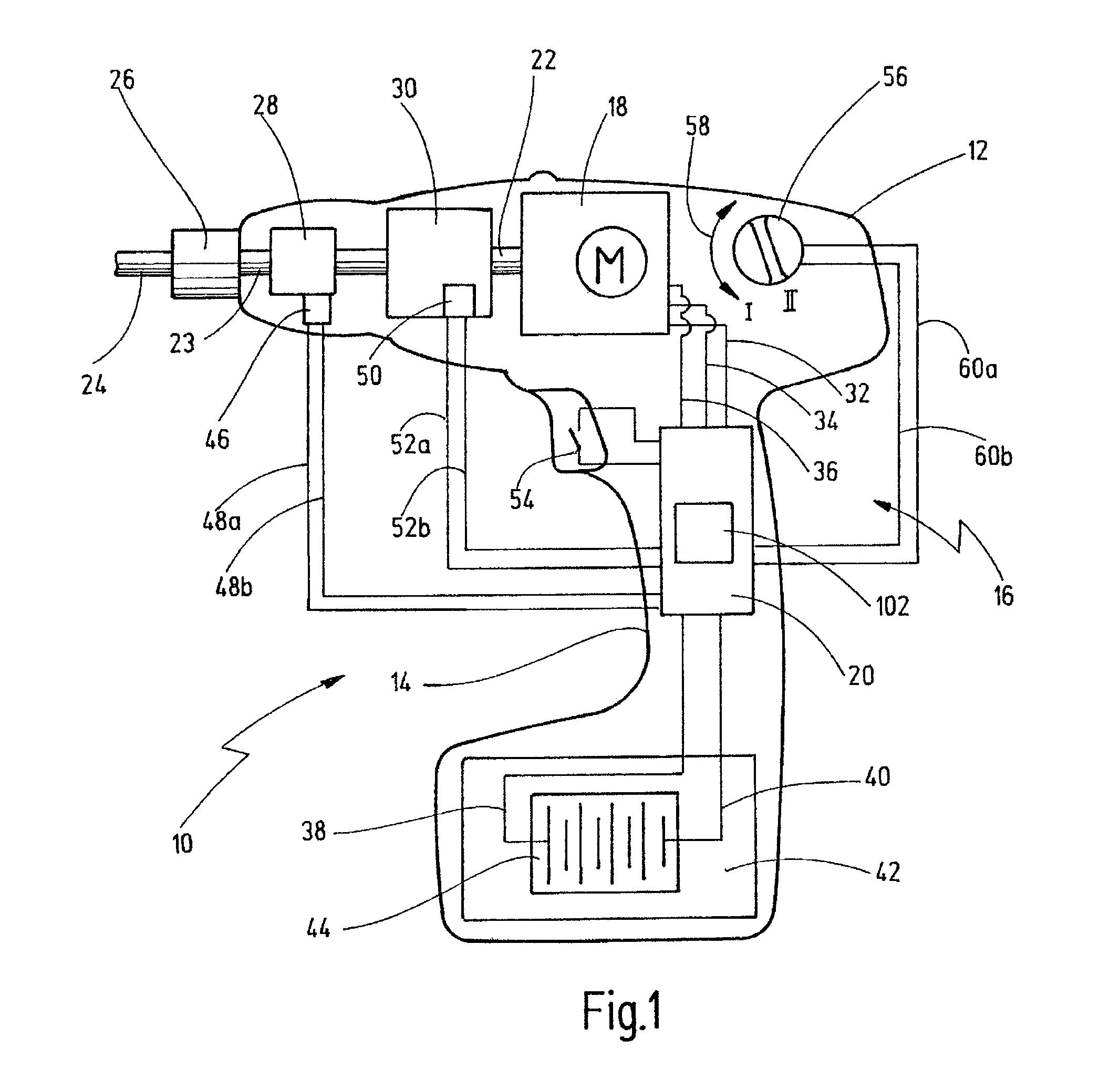
[0090]FIG. 1 shows a simplified schematic illustration of a power tool, which is denoted on the whole by 10.

[0091]By way of example, the power tool 10 is illustrated as a tool for drilling or screwing. It goes without saying that it may also be a tool for impact drilling, impact screwing, sawing, hammering, cutting, grinding or polishing, for example.

[0092]Depending on the purpose, the output motion here can be linear, rotary, intermittent or oscillating. In the present case, the power tool 10 has a housing 12 with a grip region 14, at which an operator can grip and actuate the power tool 10.

[0093]In or on the housing 12, a drive 16 is provided that has a motor 18 and a motor control 20. The motor 18 is used to drive a motor shaft 22, which is coupled to a tool spindle 23, which cooperates with a tool 24 (illustrated merely in a broken manner).

[0094]The tool 24 is fixed via a tool receptacle 26, for example a chuck, to the tool spindle 23.

[0095]A clutch 28 or a gear unit 30 can be a...


PUM


Abstract

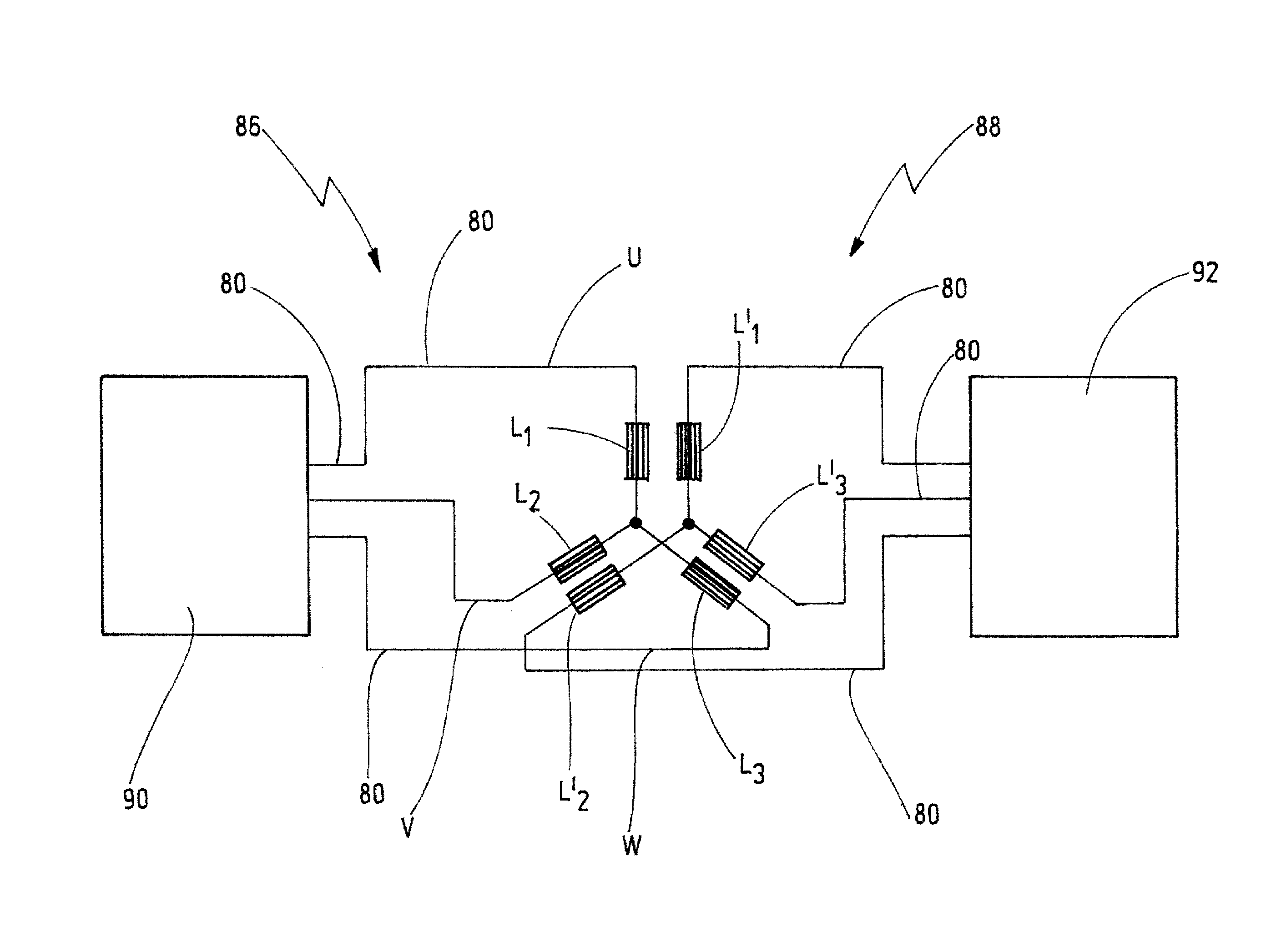
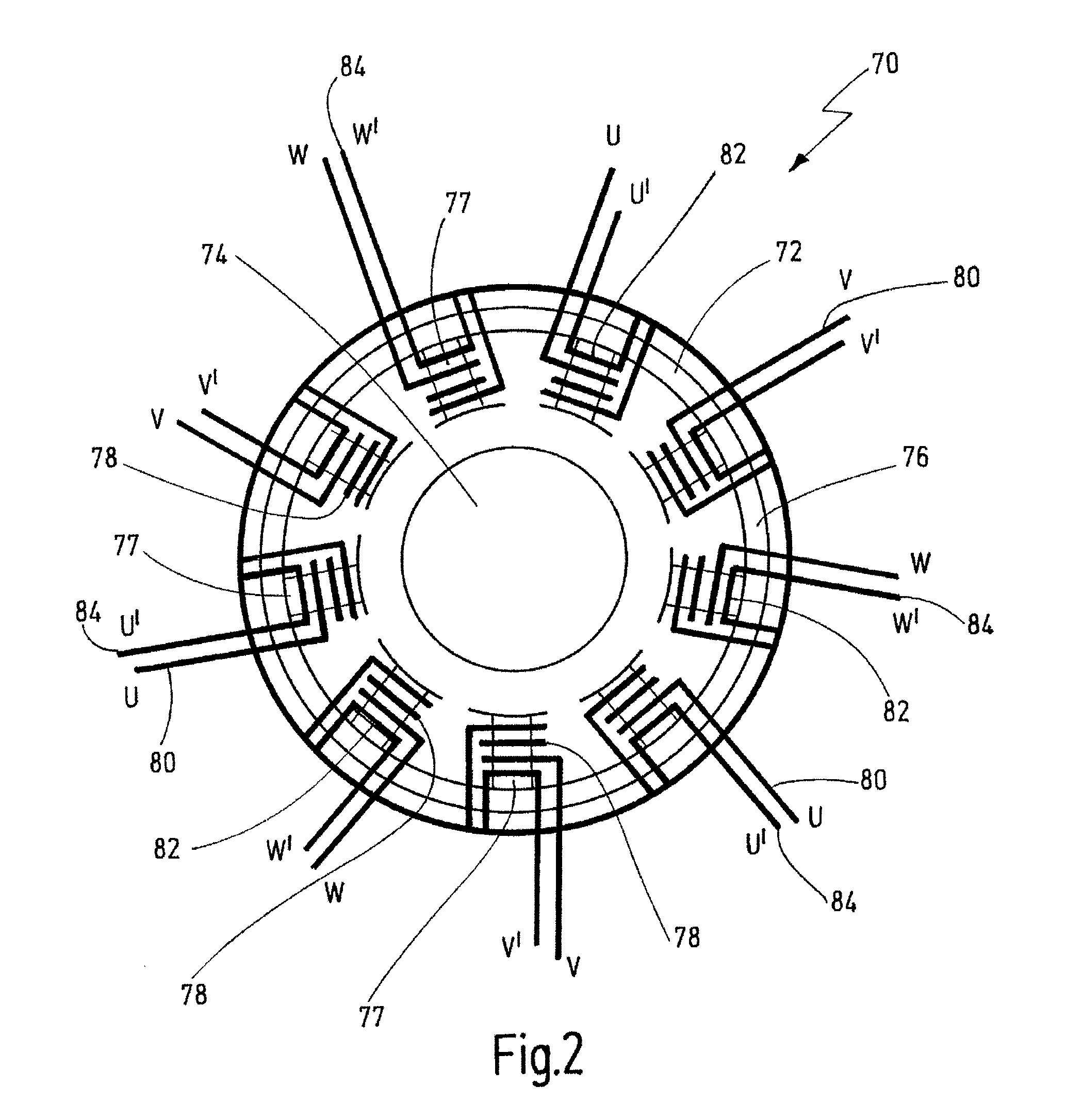
An electric drive is disclosed, in particular for a power tool, including a rotor, a stator, and a first coil arrangement, which is designed to drive the rotor by a first rotating field, and including a first motor control arrangement, which is designed to supply the first coil arrangement with electric current in order to generate a first rotating field. The stator has a second coil arrangement for generating a second rotating field. The second coil arrangement can be actuated and energized separately from the first coil arrangement so as to actuate the second coil arrangement in an arbitrary commutation sequence.

Description

BACKGROUND OF THE INVENTION[0001]The invention relates to an electric drive, in particular for a power tool, comprising a rotor, a stationary stator, and a first coil arrangement, which is designed to drive the rotor by means of a first rotating field, and comprising a first motor control arrangement, which is designed to supply the first coil arrangement with electric current in order to generate a first rotating field, wherein the electric drive has a second coil arrangement for generating a second rotating field, which is fixedly associated to the first coil arrangement and is magnetically coupled to the first coil arrangement.[0002]The invention further relates to a method for actuating an electric drive, in particular for a power tool, wherein the electric drive has a rotor and a stationary stator, wherein a first coil arrangement for generating a first rotating field is supplied with electric current by a motor control, wherein a second rotating field is generated by means of ...

Claims


Application Information

Patent Timeline
IPC IPC(8): H02P23/00
CPCH02P23/004H02P6/005H02P25/18H02P25/22H02P23/30
Inventor DIETL, LOTHAR
Owner C & E FEIN
Learn More