
Static var compensator

a compensator and thyristor technology, applied in the field of static var compensators, can solve the problems of increasing the size and cost of the thyristor valve, and not considering the voltage difference between the thyristor switches of different phases, so as to shorten the required insulation distance and reduce the size and cost

Active Publication Date: 2014-01-09
MITSUBISHI ELECTRIC CORP
View PDF26 Cites 7 Cited by
  • Summary
  • Abstract
  • Description
  • Claims
  • Application Information

AI Technical Summary

Benefits of technology

The present invention allows for a smaller and less expensive static var compensator by reducing the distance between the thyristor switches of different phases.

Problems solved by technology

It is accordingly required to provide an adequate insulation distance between the phases, which leads to a problem of an increase in size and cost of the thyristor valve.
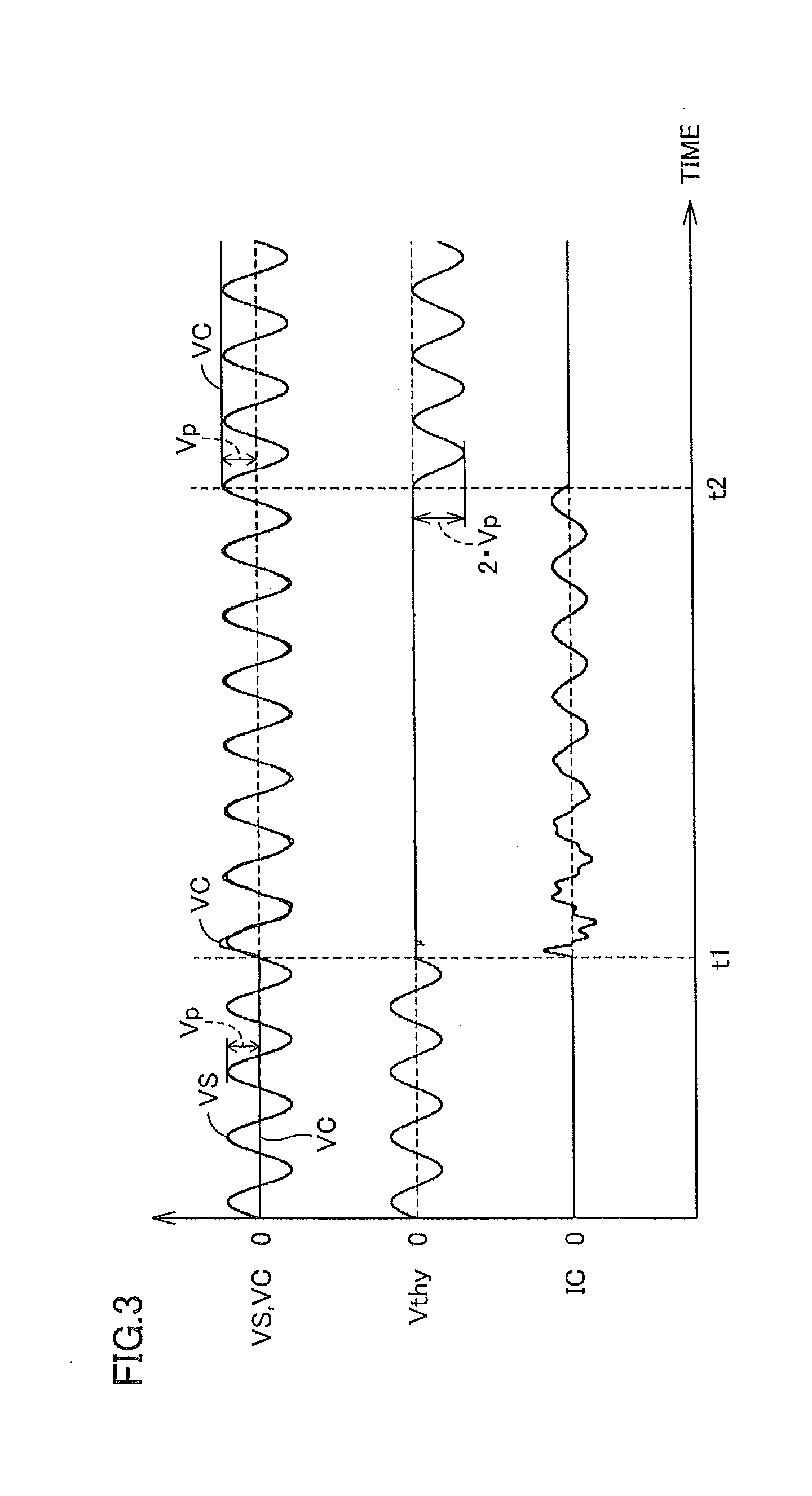
Patent Literature 1, however, does not give consideration at all to the voltage difference between the thyristor switches of different phases that occurs when the thyristor switches are turned off.

Method used


Image

  • Static var compensator
  • Static var compensator
  • Static var compensator

Examples


first embodiment

[0067]FIG. 8 is a circuit configuration diagram of a static var compensator according to a first embodiment.

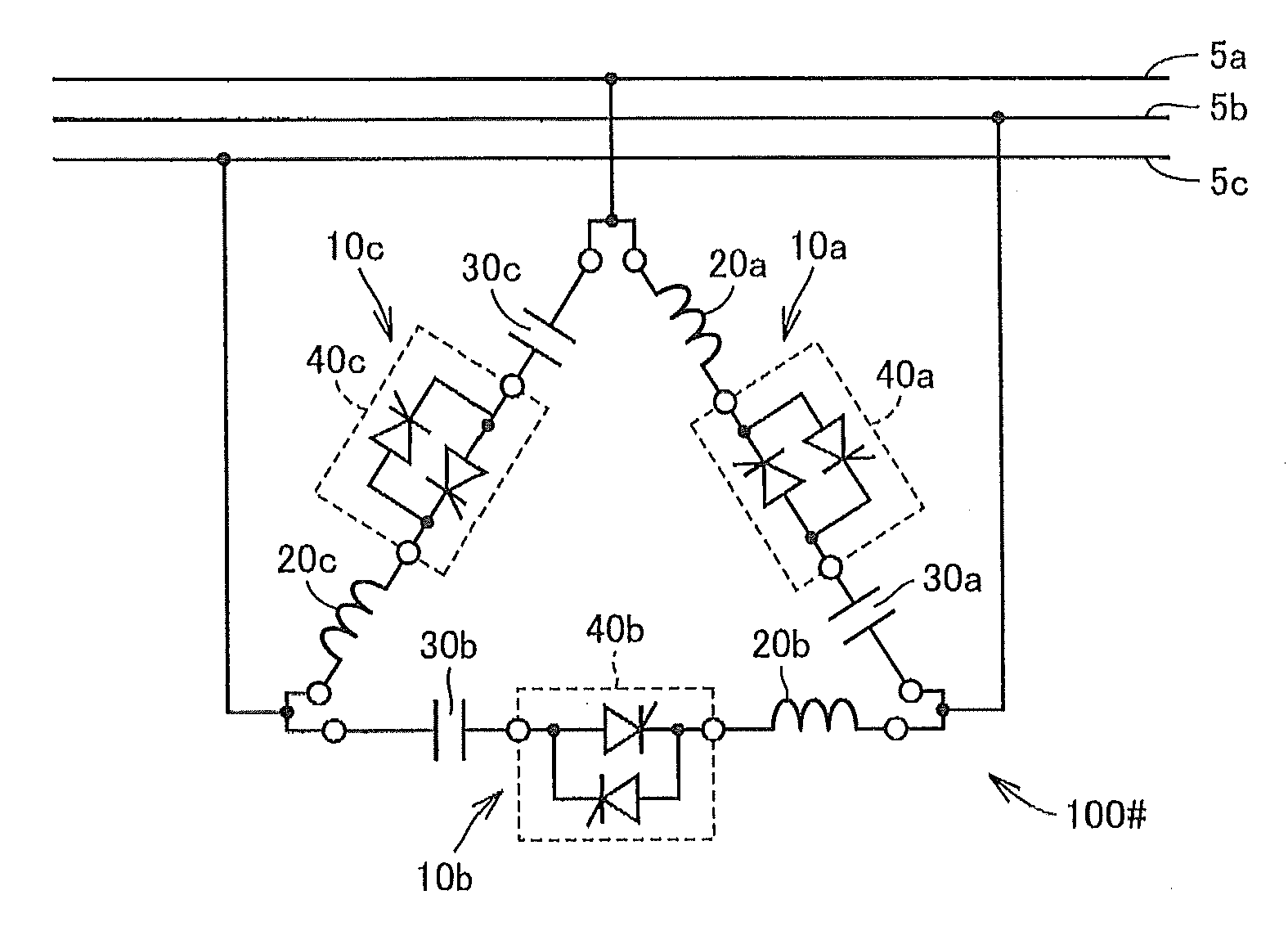
[0068]Referring to FIG. 8, static var compensator 100 according to the first embodiment includes TSCs 11a, 11b, 11c of three phases that are delta-connected to three-phase AC buses 5a, 5b, 5c.

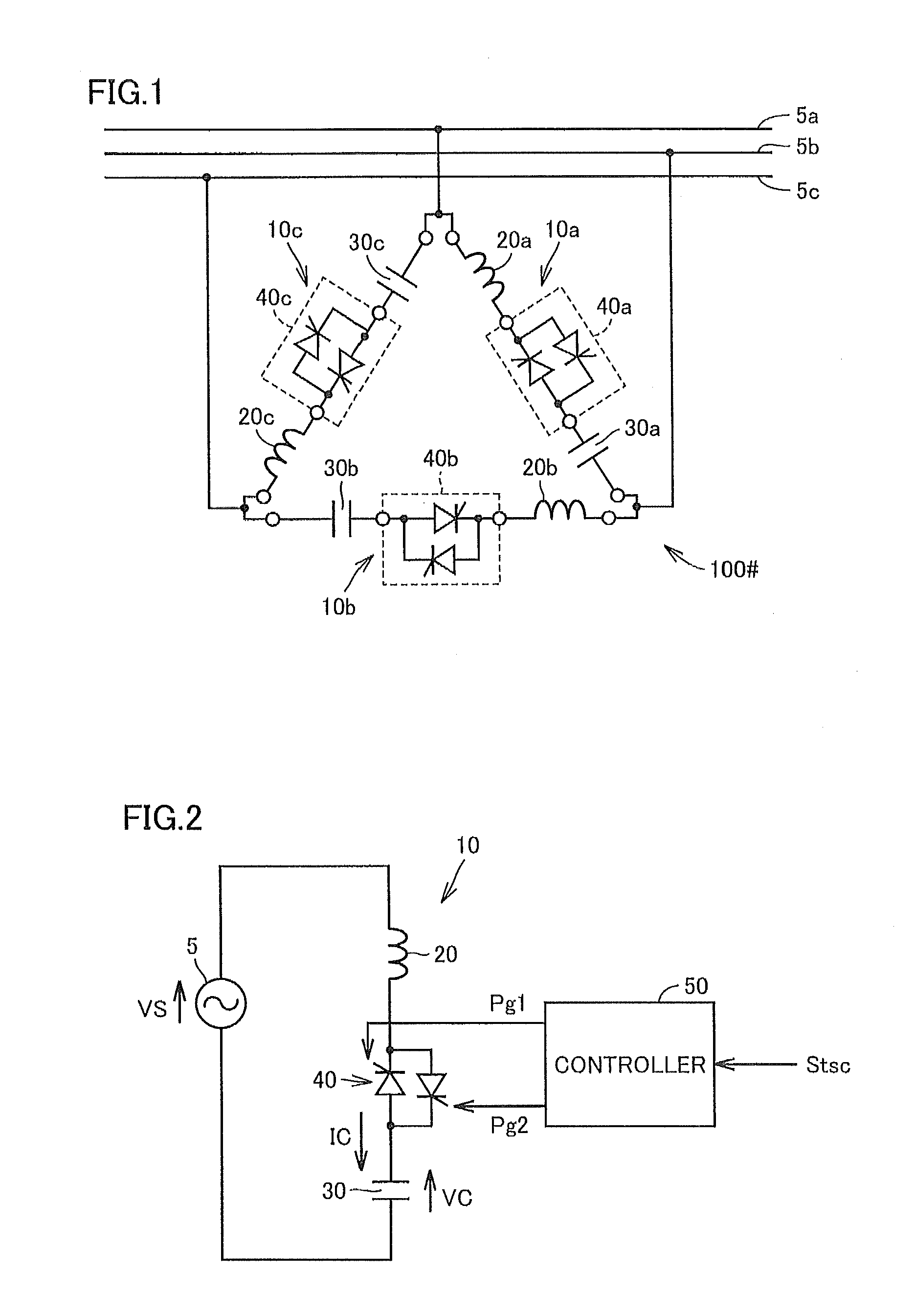
[0069]TSCs 11a, 11b, 11c each include, like TSCs 10a, 10b, 10c in FIG. 1, a reactor 20, a capacitor 30, and a thyristor switch 40 connected in series between two three-phase AC buses 5.

[0070]TSCs 11a, 11b, 11c, however, differ from TSCs 10a, 10b, 10c in FIG. 1 in that the order in which the reactor, the thyristor switch, and the capacitor are electrically connected along the loop path made up of the delta-connected TSCs is different between any one of the three phases and the remaining two phases. Therefore, the order in which the thyristor switch and the capacitor are electrically connected along the loop path is common to the two phases while this order of the remaining one phase is op...

second embodiment

[0093]Regarding the first embodiment, an example of the configuration of the thyristor valve has been described in which thyristor switch units 70a to 70c of three phases are vertically stacked on each other. Regarding a second embodiment, a modification of the configuration of the thyristor valve will be described.

[0094]FIG. 11 is a conceptual diagram illustrating a first example of the configuration of the thyristor valve applied to a static var compensator according to the second embodiment.

[0095]Referring to FIG. 11, a thyristor valve 201 according to the first example of the second embodiment differs from thyristor valve 200 shown in FIG. 9 in that thyristor switch units of two phases among thyristor switch units 70a, 70b, 70c of the three phases are stacked on each other, while the thyristor switch unit of the remaining one phase is separately arranged in the form of a single stage. In FIG. 11, the electrical connection between TSCs 11a, 11b, 11c and three-phase AC buses 5a, 5...


PUM


Abstract

Three-phase TSCs are delta-connected to three-phase AC buses. Each TSC includes a reactor, a capacitor, and a thyristor switch that are electrically connected in series. The thyristor switches of the three phases are arranged so that the terminal-to-terminal distance between respective thyristor switches of respective phases are not uniform. The three-phase TSCs are configured so that the TSCs of two of the three phases having a shortest terminal-to-terminal distance therebetween are opposite to each other in terms of connection order in which the thyristor switch and the capacitor are electrically connected along a loop path made up of the delta-connected TSCs.

Description

BACKGROUND OF THE INVENTION[0001]1. Field of the Invention[0002]The present invention relates to a static var compensator, and more specifically to a static var compensator using a TSC (Thyristor Switched Capacitor).[0003]2. Description of the Background Art[0004]In order to compensate for reactive power of an electric power system, TSCs are used. Specifically, the TSCs that are series circuits each including a capacitor and a thyristor are connected in parallel to a transmission line to thereby supply leading reactive power to the system.[0005]For example, Japanese Patent Laying-Open No. 62-244268 (hereinafter Patent Literature 1) discloses TSCs formed by delta-connecting three-phase series circuits each including a reactor, a capacitor, and a thyristor switch. Patent Literature 1 discloses a triggering method for thyristor switches forming the TSCs in order to reduce a difference of the triggering timing between the thyristor switches. Following the triggering method according to ...

Claims


Application Information

Patent Timeline
Patent Type & Authority Applications(United States)
IPC IPC(8): G05F1/70
CPCG05F1/70H02M1/4208Y02E40/30
Inventor MORI, OSAMUTAKEDA, MASATOSHIOGUSA, SHINICHI
Owner MITSUBISHI ELECTRIC CORP
Learn More