Method and apparatus for printhead control

a technology of printhead and control method, applied in the field of printing devices, to achieve the effect of higher quality printing and more efficient us

Active Publication Date: 2014-01-09
ZEBRA TECH CORP
View PDF3 Cites 11 Cited by
  • Summary
  • Abstract
  • Description
  • Claims
  • Application Information

AI Technical Summary

Benefits of technology

[0107]As mentioned above, the print engine 170 may reconfigure the interface to the printhead 130 based on the detected type of printhead 130 and the determined width of the printhead 130. Because printheads can have different operating specifications, being able to detect and adapt the interface and subsequent operation of the print engine 170 based on the detected printhead can result in more efficient and higher quality printing.
[0108]Many aspects of the present invent...

Problems solved by technology

Applicant has identified a number of deficiencies and p...

Method used


Image

  • Method and apparatus for printhead control
  • Method and apparatus for printhead control
  • Method and apparatus for printhead control

Examples


Embodiment Construction

[0038]Some embodiments of the present invention will now be described more fully hereinafter with reference to the accompanying drawings, in which some, but not all embodiments of the invention are shown. Indeed, various embodiments of the invention may be embodied in many different forms and should not be construed as limited to the embodiments set forth herein; rather, these embodiments are provided so that this disclosure will satisfy applicable legal requirements. Like reference numerals refer to like elements throughout.

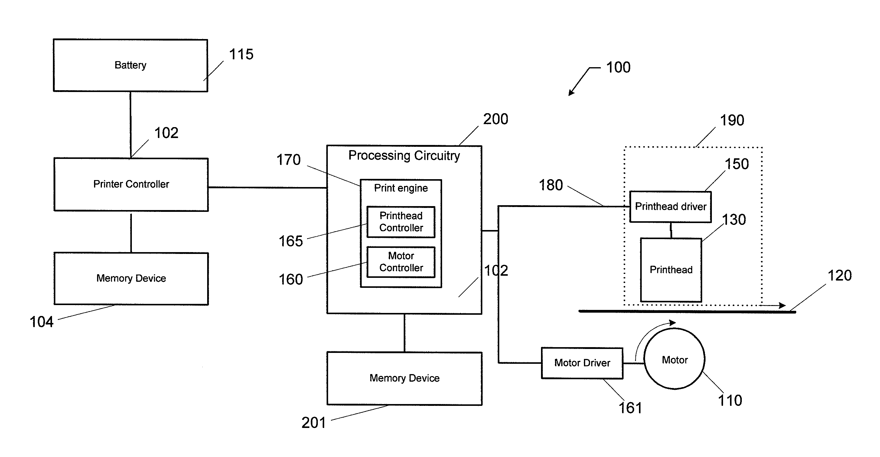
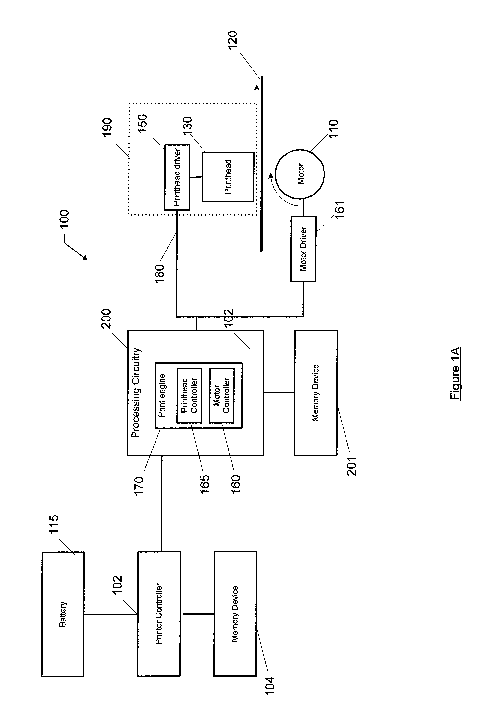
[0039]FIG. 1A is a schematic block diagram of an example printing device 100 according to some example embodiments. The printing device 100 may be a direct thermal printer, a thermal transfer printer, or the like. The printing device 100 may be a stand-alone unit (e.g., a handheld printer) or may be integrated into a larger apparatus, such as an ATM, gas pump, point-of-sale device, or the like.

[0040]A printhead assembly 190 may include a printhead driver 150 and...


PUM


Abstract

A method, apparatus, and computer program product are described herein for controlling a printing device. In an example embodiment, a print line is divided into frames and frame dot states are determined based on neighboring frame dot states. Maximum motor speeds of the printing device may be adjusted so that actual motor speeds change gradually during printing. The print engine may detect a printhead type by sending a signal to the printhead and receiving a response.

Description

CROSS REFERENCE TO RELATED APPLICATIONS[0001]This application claims the benefit of priority to U.S. Provisional Application No. 61 / 583,428, which was filed Jan. 5, 2012 and is hereby incorporated by reference in its entirety.TECHNICAL FIELD[0002]The present invention relates generally to printing devices. Some aspects of the invention relate specifically to thermal printing devices while other aspects may be implemented in various other types of printing devices.BACKGROUND[0003]Thermal printers are used in a variety of different applications, such as, for example, receipt dispensing systems for ATMs and point-of-sale devices. Various types of thermal printers have been developed including direct thermal printers, thermal transfer printers, dye-sublimation thermal printers, or the like. To generate a printed media, such as a receipt, a printer may include a thermal printhead that applies energy to series of printhead dots (e.g., heating elements) to print respective dot images on th...

Claims


Application Information

Patent Timeline
IPC IPC(8): G06K15/02G06K15/10
CPCG06K15/028G06K15/10G06K15/1827B41J2/32B41J2/355B41J2/3555
Inventor HEGARTY, PATRICK J.LAMONTAGNE, MICHAEL L.
Owner ZEBRA TECH CORP
Why Eureka
Try Eureka