Optical lens systems

a technology of optical lenses and optical lenses, applied in the field of optical systems, can solve the problems of image degradation, optical systems that are larger and heavier than others, and achieve the effect of reducing the size and weight of the optical system

Inactive Publication Date: 2014-01-09
FM ASSETS
View PDF1 Cites 5 Cited by
  • Summary
  • Abstract
  • Description
  • Claims
  • Application Information

AI Technical Summary

Benefits of technology

[0054]The lens system provi

Problems solved by technology

Every time a light ray has to travel from air to glass to air again, there is some degradation of the image.
Further the Pechan prism or it

Method used


Image

  • Optical lens systems
  • Optical lens systems
  • Optical lens systems

Examples


Embodiment Construction

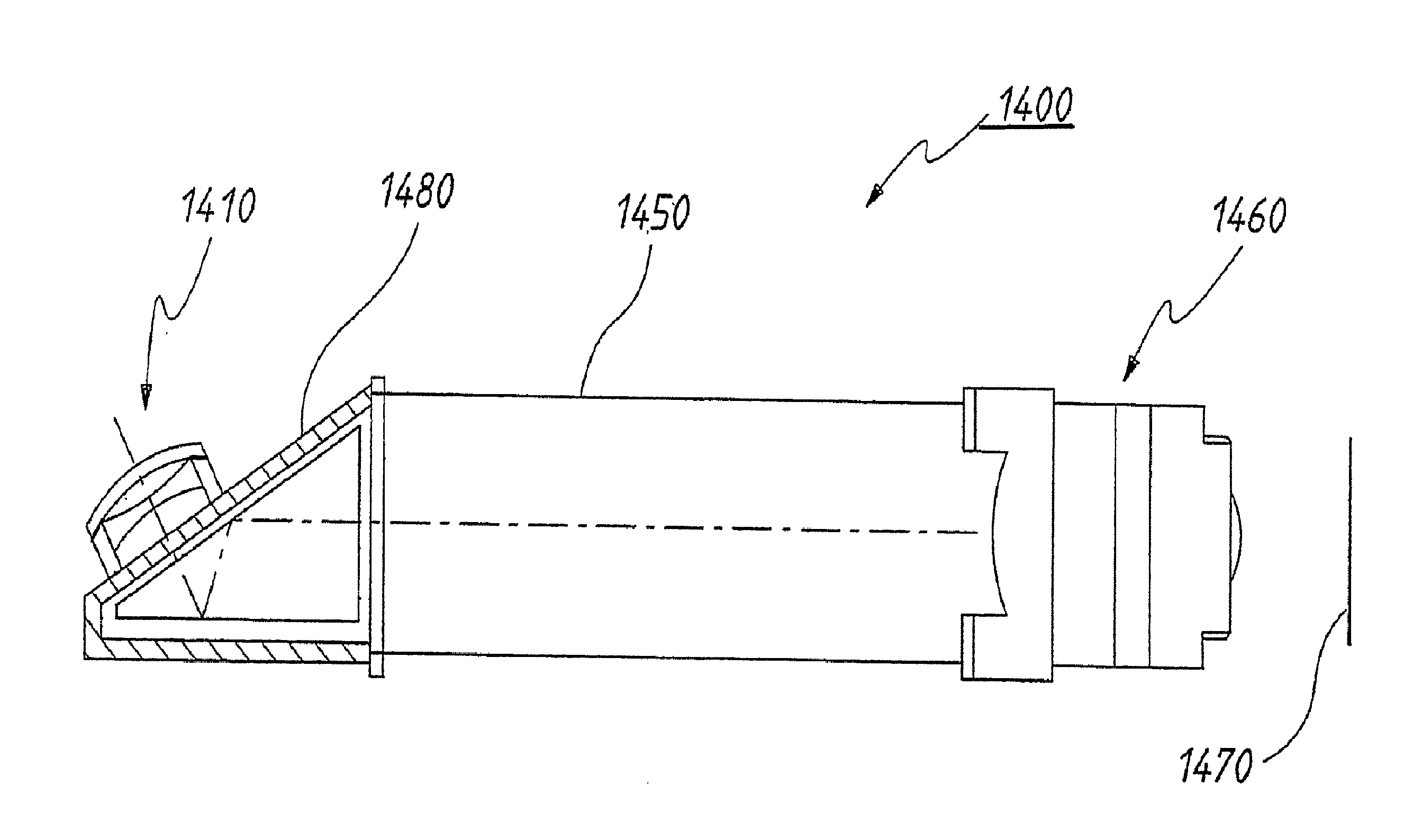
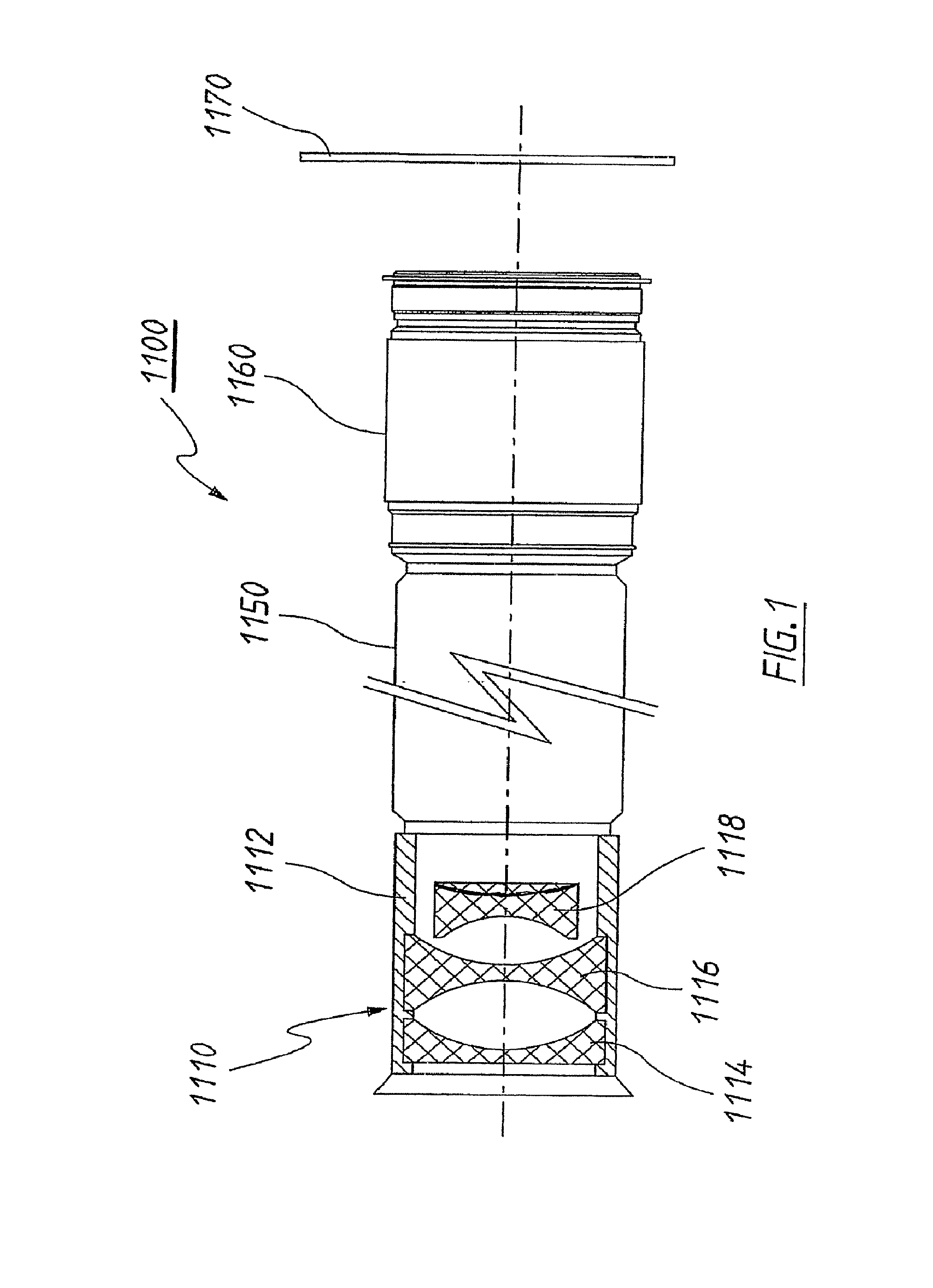
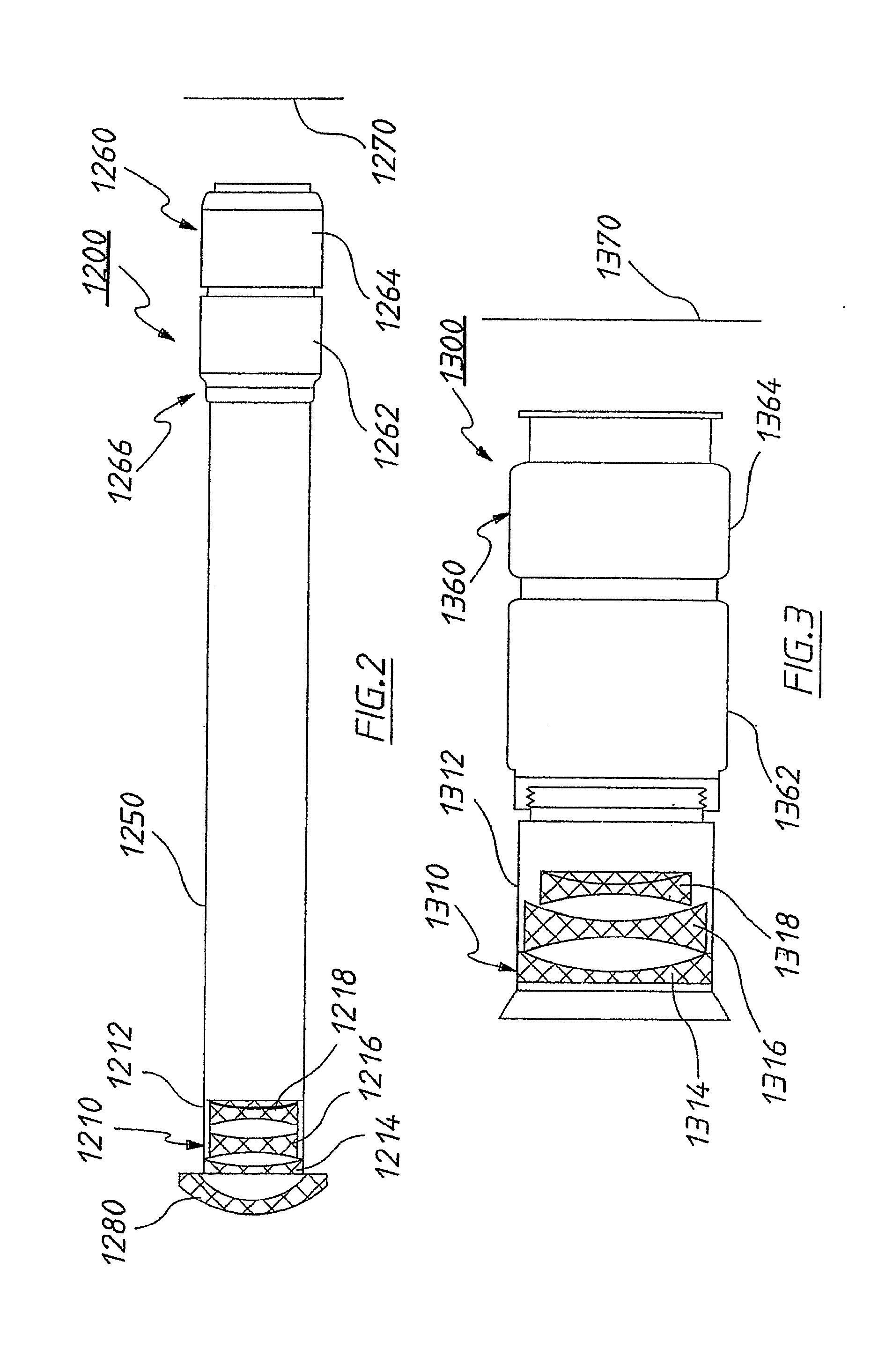
[0074]Wide-angle, deep-field, close-focusing optical systems are disclosed hereinafter. Optical lens attachments and cameras comprising optical lens attachments are also described hereinafter. Still further, double-swivel optical lens system and cameras comprising such double-swivel optical lens systems are described herein after. In the following description, numerous specific details, including particular film formats, lens materials, particular angled prism units, coupling mechanisms, barrel lengths, prism units, and the like are set forth. However, from this disclosure, it will be apparent to those skilled in the art that modifications and / or substitutions may be made without departing from the scope and spirit of the invention. In other circumstances, specific details may be omitted so as not to obscure the invention.

[0075]Where reference is made in any one or more of the accompanying drawings to features, which have the same or similar reference numerals, those features have f...


PUM


Abstract

Optical lens attachments and cameras are disclosed. The attachment comprises a coupling mechanism for mating engagement with at least one of a camera and an optical lens. A barrel is coupled at one end to the coupling mechanism. A negative lens unit is coupled to the other end of elongated barrel. A diopter lens is disposed between the barrel and the coupling mechanism. The coupling mechanism, the diopter lens, and the barrel are aligned with an optical axis. Also disclosed is a double swivel optical system, comprising a negative lens unit, a mirror oriented at an angle to the optical axis of the negative lens unit, a roof prism for rotating incident light rays by 90 degrees and inverting an image, a rotation mechanism permitting rotation of the negative lens unit about a vertical axis, an image rotator comprising a prism that can invert an image, the prism disposed within the image rotator, and another rotation mechanism permitting rotation of the roof prism about an optical axis of the image rotator.

Description

RELATED PATENT APPLICATIONS[0001]This application is a divisional application of and claims priority from U.S. patent application Ser. No. 12 / 063,530, filed in the U.S. on May 27, 2008, and which is incorporated by reference herein. This patent application also claims the benefit of, and is entitled to, the earlier filing dates of:[0002](1) Australian Provisional Patent Application No. 2005904334 filed on 11 Aug. 2005 in the name of Global Bionic Optics Pty Ltd (Attorney Ref: 730137:SDB);[0003](2) Australian Provisional Patent Application No. 2005905635 filed on 12 Oct. 2005 in the name of Global Bionic Optics Pty Ltd (Attorney Ref: 736362:SDB); and[0004](3) International (PCT) Patent Application No. PCT / AU2005 / 001675 filed on 3 Nov. 2005 in the names of Global Bionic Optics Pty Ltd and James Albert Frazier (Attorney Ref: 730137C:SDB);[0005](4) Australian Provisional Patent Application No. 2006902230 filed on 28 Apr. 2006 in the name of Global Bionic Optics Pty Ltd (Attorney Ref: 76...

Claims


Application Information

Patent Timeline
IPC IPC(8): G02B15/22G02B17/08
CPCG02B15/22G02B17/08G02B5/04G02B13/0095G02B13/06G02B27/642G03B17/14G03B17/17G02B13/00G02B13/24G02B17/00
Inventor FRAZIER, JAMES ALBERT
Owner FM ASSETS
Why Eureka
Try Eureka